Step 6:Ensure that no voltage is present between the positive terminal and negative terminal
at the DC inputs using a suitable measuring device.
Step 7:
Loosen and remove the Grid connector.
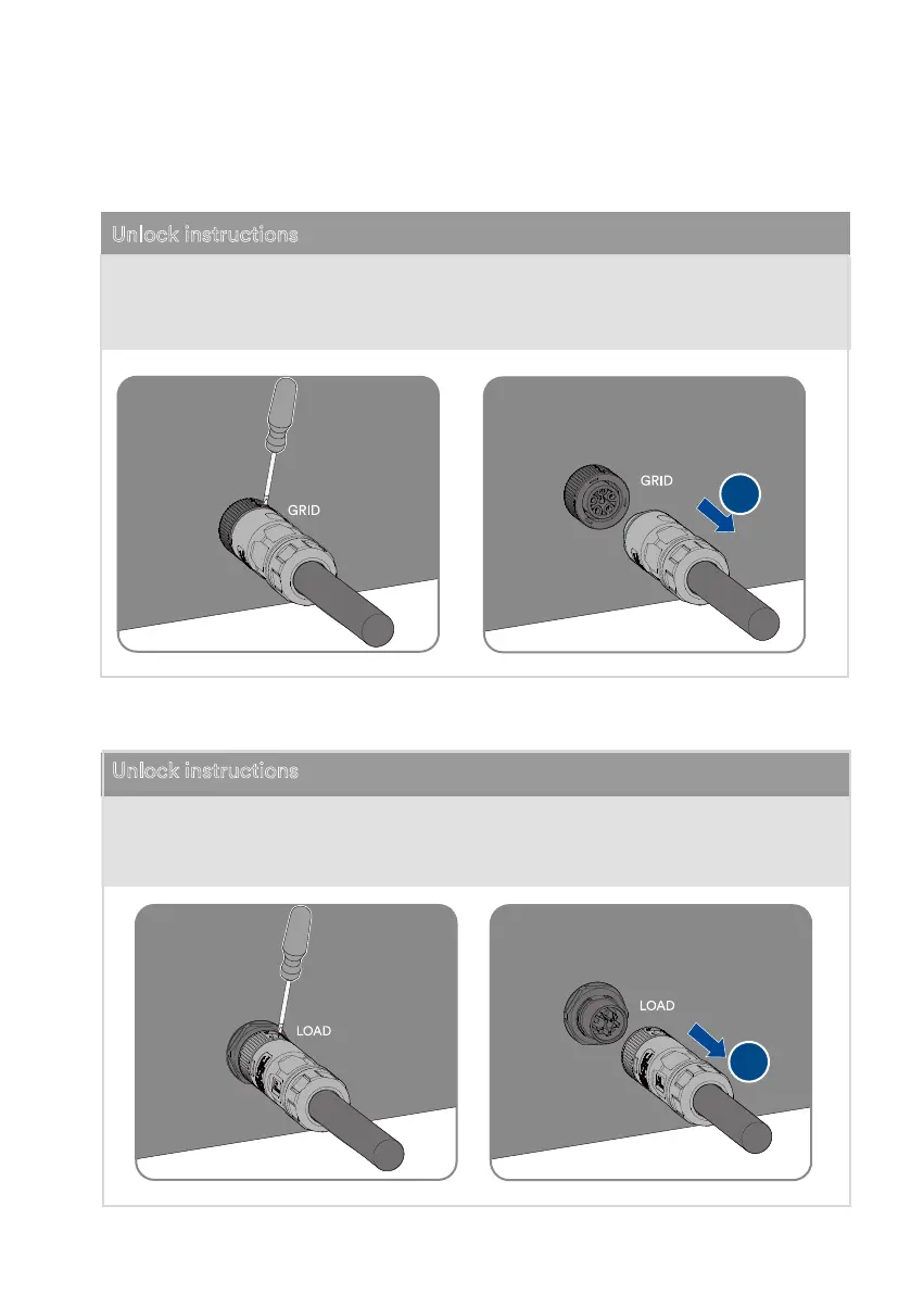
Unlock instructions
① se the athead screwdriver installa
tion icon
② Remove the female end of the cable to
unlock the account.
Unlock instructions
Step 8:
Loosen and remove the Backup Load connector.
2
2
① se the athead screwdriver installa
tion icon
② Remove the female end of the cable to
unlock the account.
UM0035_ASW05-12kH-T2-T3_EN_V01_0523