15
Locations and Functions of Parts
Chapter 1 Overview
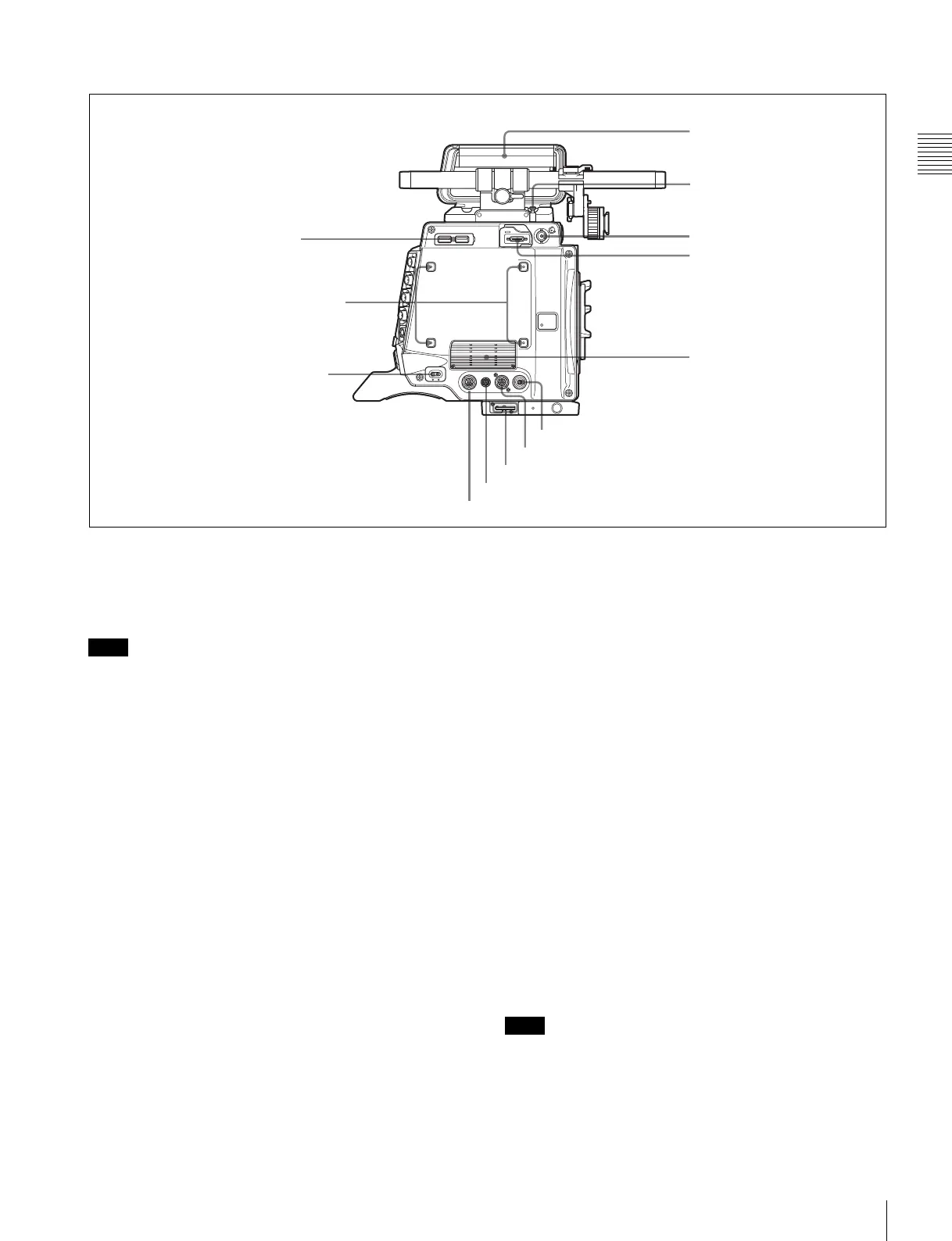
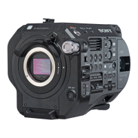
Left panel
a USB connectors
USB 2.0 standard connector. Connect a CBK-WA01 Wi-Fi
Adapter (optional) to enable communication with wireless
LAN devices.
When operating the system with a CA4000 connected,
network connection via this connector is not possible.
b Accessory receptacles
For mounting accessories using M3 screws. The depth of
the screws is 5 mm (
7
/
32
inch).
c CAM POWER switch
Turns the camera power supply ON/OFF.
d DC OUT 12V 4A (12 V DC supply output)
connector
Supplies 12 V DC power source to accessories, when the
CAM POWER switch is in the ON position.
e DC OUT 24V 4A (24 V DC supply output)
connector
Supplies 24 V DC power source to accessories when there
is a 24 V DC supply connected to the DC IN connector and
the CAM POWER switch is in the ON position.
f Wrench box
Stores a 3 mm (
1
/
8
inch) wrench for attaching/detaching
the handle.
g LENS connector (12-pin)
Controls the aperture remotely with the connection of a
commercially-available iris servo unit.
h EXT. I/O (external control) connector (5-pin)
It is not used in this version.
i Handle
The handle is attached to the top of the camera head at the
factory. It has two sizes of screw holes (
3
/
8
",
1
/
4
") for
accessories on the upper side.
j Measure hook/focus reference mark
Use as reference for focusing.
For actual measurement of the distance from a subject, you
can fix the end of a tape measure to the hook.
When shooting shallow depth-of-field images in high
resolution, it is recommended that you adjust the focus
using the camera or viewfinder magnification function.
k SDI OUT2 connector (BNC type)
Outputs the SDI2 Look (single link) signal.
l VF connector (26-pin, for DVF-EL100)
Connects to the DVF-EL100 viewfinder (option).
To reduce OLED burn-in, use the DVF-EL100 switch to
turn VF DISPLAY (viewfinder display function) On/Off.
c CAM POWER switch
d DC OUT 12V 4A connector
e DC OUT 24V 4A connector
f Wrench box
g LENS connector
h EXT. I/O connector
i Handle
j Measure hook/
focus reference mark
b Accessory receptacles
a USB connectors
k SDI OUT2 connector
l VF connector (for DVF-EL100)
m Ventilation holes (exhaust)
Note
Note