43
Setting the Output Signal
Chapter 3 Basic Adjustments and Settings
When “Through” is selected, a L3D file is not used, and 1D
LUT is fixed at S-Log3 and Color is fixed at S-
Gamut3.Cine.
The following can also be specified, independent of the
selected look.
ASC CDL: Sets whether to apply ASC CDL in the check
box. Selects an imported CCC file or CDL file.
The SDI1 system supports “Graded ACES,” “Look
Profile,” “3D LUT,” and “L3D File” settings that perform
color conversion using a built-in 3D LUT. The F65
employs a 3D LUT with 17×17×17 lattice to obtain a
contour line signal for areas of smoothly varying luminous
intensity.
The recording signal is not affected, allowing the
processing to be improved using a color grading tool that
performs color conversion employing a higher-degree 3D
lattice grid.
Adjusting the SDI OUT2 output signal
You adjust the image on the <SDI2 Look> page of the VF/
SDI menu.
<SDI2 Look> page
Select
Sets the look of the output image on the SDI OUT2
connector.
The default setting is Color/LUT.
S-Log2/S-Gamut: Outputs images in S-Log2 or S-
Gamut. This setting is suitable for monitoring the
full range of the image, from dark areas to high-
intensity areas.
Color/1D LUT: Outputs images with the specified
Color and 1D LUT.
For details, see “When Color/1D LUT is selected
for Select” (page 42) for SDI OUT1.
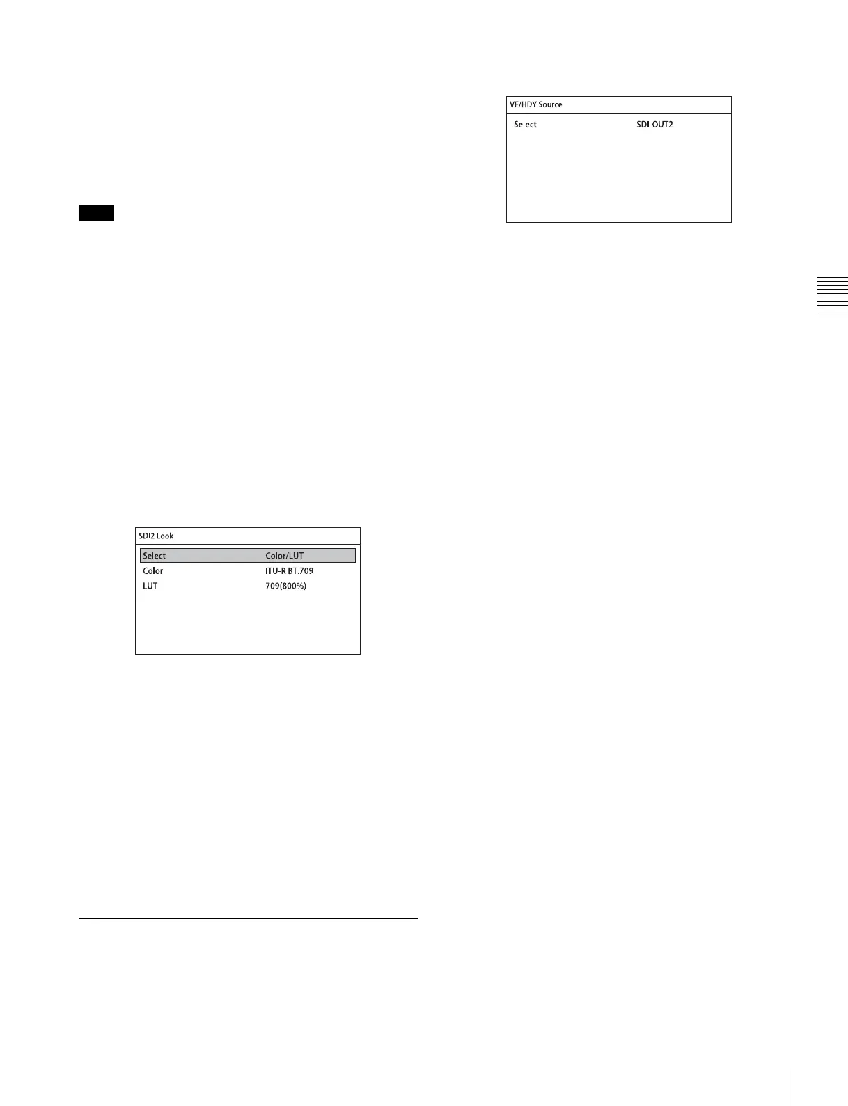
3-6-2 Selecting the Viewfinder
Output Signal
This selects the video signals for output on the VF and HD-
Y connectors.
<VF/HD-Y Source> page
Select
Selects the image for output.
The default setting is SDI-OUT2.
SDI-OUT1: Selects the image that is output on the
SDI OUT1 connector.
SDI-OUT2: Selects the image that is output on the
SDI OUT2 connector.
Note