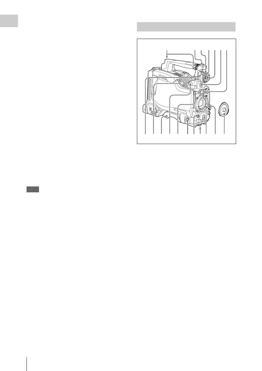
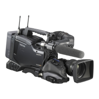
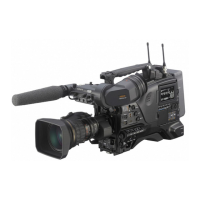
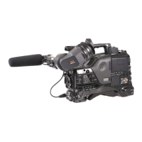
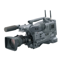
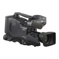
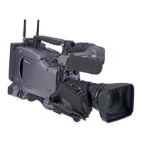
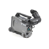
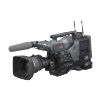
Locations and Functions of Parts and Controls
12
Chapter 1 Overview
c DC IN (DC power input) connector
(XLR type, 4-pin, male)
To operate the camcorder from an AC power
supply, connect an optional DC power cord to this
terminal and then connect the cord to the DC
output terminal of the BC-L70, BC-L160, or
another battery charger.
d DC OUT 12V (DC power output)
connector (4-pin, female)
Supplies power for a WRR-860A/861/862 UHF
Synthesized Diversity Tuner (not supplied)
(maximum 0.5 A).
Do not connect any equipment other than the
UHF synthesized diversity tuner.
e Battery attachment shoe
Attach a BP-GL95/GL65/L60S/L80S Battery
Pack. Alternatively, you can attach an AC-
DN2B/DN10 AC Adaptor to operate the
camcorder on AC power supply.
For details about how to attach the battery or AC
adaptor, see “Preparing a Power Supply” on page
33. For information about attaching a synthesized
tuner, see “Attaching a UHF portable tuner (for a
UHF wireless microphone system)” on page 44.
Note
For your safety, and to ensure proper operation of the
camcorder, Sony recommends the use of the following
battery packs: BP-GL95, BP-GL65, BP-L60S, and BP-
L80S.
a Shoulder strap fitting
Attach the supplied shoulder strap (see page 48).
b Accessory fitting shoe
Attach an optional accessory such as a video light
(see page 48).
c Viewfinder front-to-back positioning
lever
To adjust the viewfinder position in the front-to-
back direction, loosen this lever and the LOCK
knob. After adjustment, retighten this lever and
the LOCK knob.
d Viewfinder left-to-right positioning ring
Loosen this ring to adjust the left-to-right position
of the viewfinder (see page 35).
e Viewfinder fitting shoe
Attach an optional viewfinder.
f VF (viewfinder) connector (20-pin)
Connect an optional viewfinder.
Consult a Sony representative for information about
available viewfinders.
g Lens mount securing rubber
After locking the lens in position using the lens
locking lever, fit this rubber over the lower of the
two projections. This fixes the lens mount,
preventing it from coming loose.
Accessory attachments
5674231
890qaqs qd qgqh qj
qk
qf


 To Next Page