Locations and Functions of Parts and Controls
15
Chapter 1 Overview
For details, see “Assigning functions to ASSIGN
switches” on page 204.
b COLOR TEMP. (color temperature)
button
Press to light the button and change the color
temperature for shooting. You can use this as an
ASSIGN (assignable) switch
(see page 204).
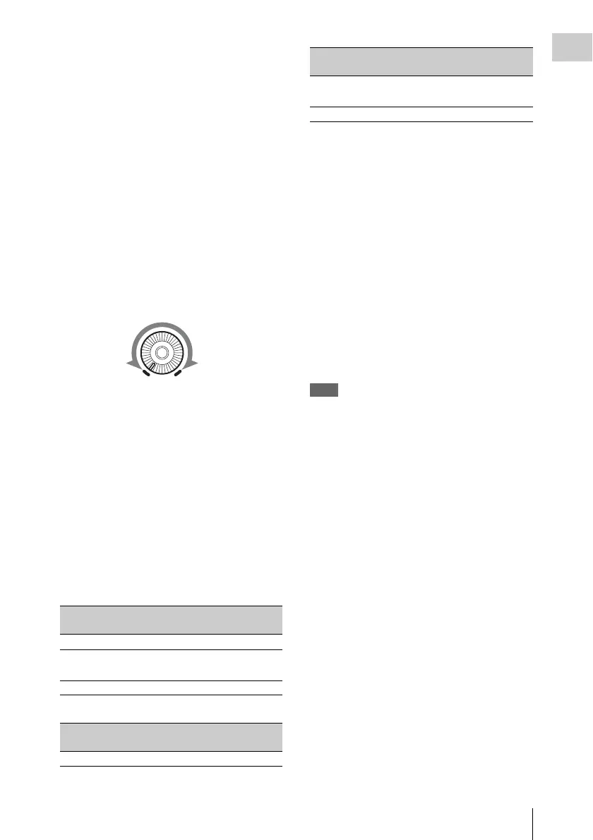
c ALARM (alarm tone volume
adjustment) knob
Controls the volume of the warning tone that is
output via the built-in speaker or optional
earphones. When the knob is turned to the
minimum position, no sound can be heard.
However, if the MIN ALARM VOL item on the
AUDIO-1 page of the MAINTENANCE menu is
set to SET, the alarm tone is audible even when
this volume control is at the minimum position.
d MONITOR (monitor volume
adjustment) knob
Controls the volume of the sound other than the
warning tone that is output via the built-in speaker
or optional earphones. When the knob is turned to
the minimum position, no sound can be heard.
e MONITOR (audio monitor selection)
switches
By means of combinations of the two switches,
you can select audio that you want to hear through
the built-in speaker or optional earphones.
Position of down-side switch: CH-1/2
Position of down-side switch: CH-3/4
a) By connecting stereo headphones to the EARPHONE
jack on the rear of the unit, you can hear the audio in
stereo. (On the AUDIO-1 page of the
MAINTENANCE menu, HEADPHONE OUT must
be set to STEREO.)
f VDR SAVE/STBY (VDR save/standby)
switch
Switches the status of the power supply to the
video disc drive (referred to as “VDR”) while
recording is stopped (STOP) or paused (REC
PAUSE).
SAVE: The disc stops rotating and some
functions are disabled. Power consumption is
lower than when the camcorder is in STBY
mode. Battery life is extended.
STBY: Recording to the disc starts immediately
when the REC START button is pressed.
Note
An internal operating sound may be recorded at the start
of recording when the VDR SAVE/STBY switch is set to
SAVE.
g GAIN selector
Switches the gain of the video amplifier to match
the lighting conditions during shooting. The gains
corresponding to the L, M, and H settings can be
selected in the menu. (The factory settings are
L=0 dB, M=6 dB, and H=12 dB.)
When this switch is adjusted, the new setting
appears on the setting change/adjustment
progress message display area of the viewfinder
screen for about three seconds.
For details, see “Setting gain values for the GAIN
selector positions” on page 203.
h OUTPUT/DCC (output signal/dynamic
contrast control) switch
Switches the video signal, which is output to the
VDR, viewfinder, and video monitor from the
camera section, between the following two.
BARS: Outputs the color bar signal.
CAM: Outputs the video signal from the camera.
When this is selected, you can switch DCC
1)
on and off.
Position of up-side
switch
Audio output
CH-1/CH-3 Channel 1 audio
MIX Channels 1 and 2 mixed
audio (stereo)
a)
CH-2/CH-4 Channel 2 audio
Position of up-side
switch
Audio output
CH-1/CH-3 Channel 3 audio
ALARM
Minimum Maximum
MIX Channels 3 and 4 mixed
audio (stereo)
a)
CH-2/CH-4 Channel 4 audio
Position of up-side
switch
Audio output


 To Next Page