HT-S350/SD35
10
Sony CONFIDENTIAL
For Authorized Servicer
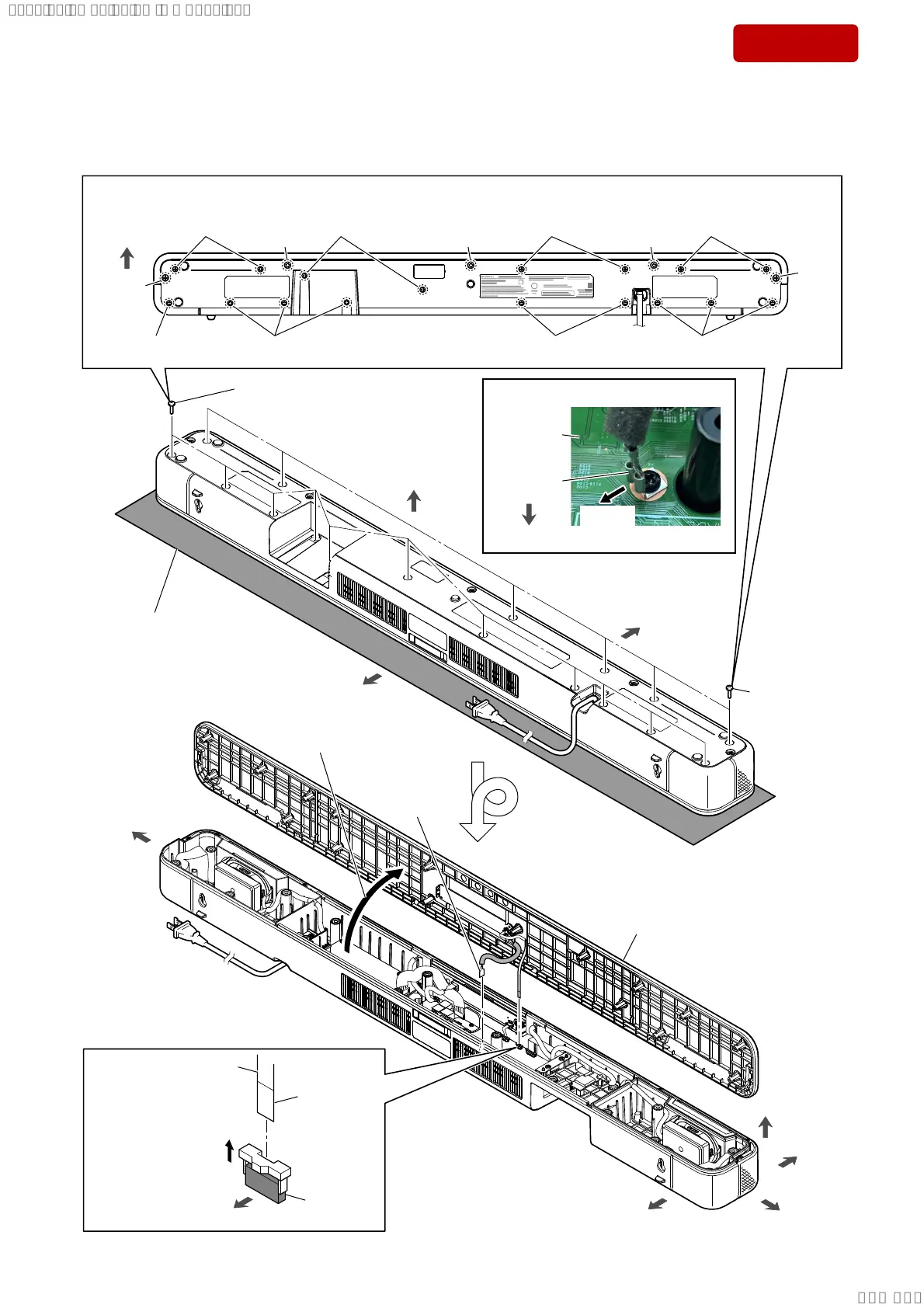
Note: Follow the disassembly procedure in the numerical order given.
2-2. TOP PANEL BLOCK
rear side
front side
– Bottom view –
Ÿ
1 two screws
(BTP3 u 10)
1 three screws
(BTP3 u 10)
six screws
(BTP3 u 10)
eleven screws
(BTP3 u 10)
soft cloth, etc.
Note 2:
When working with the top
side facing down, lay a soft
cloth, etc. so as not to damage.
ŸŸŸ
Ÿ
1 two screws
(BTP3 u 10)
1 two screws
(BTP3 u 10)
1 two screws
(BTP3 u 10)
1 two screws
(BTP3 u 10)
1 three screws
(BTP3 u 10)
1 screw
(BTP3 u 10)
Turn over.
rear side
front side
front side
left side
right side
2 Open the top panel block
in the direction of the arrow.
6
top panel block
5
terminal
(See Fig. A)
3
Unlock the
connector.
connector
(CN6)
terminal side
rear side
4 Draw the FFC (6 core)
out of the connector.
Note 1:
:KHQGLVDVVHPEOLQJWKHWRSSDQHOEORFNUHPRYLQJWKHILYHVFUHZVDWWKHŸPDUNVFUHZVLVQRWQHFHVVDU\
top side
bottom side
< Fig. A >
rear side
,QVWDOODWLRQGLUHFWLRQIRUWKHWHUPLQDO
terminal
MAIN
board
caulking
direction
– Top view –
SYSSET
2019/02/1301:27:25(GMT+09:00)