HT-S350/SD35
19
Sony CONFIDENTIAL
For Authorized Servicer
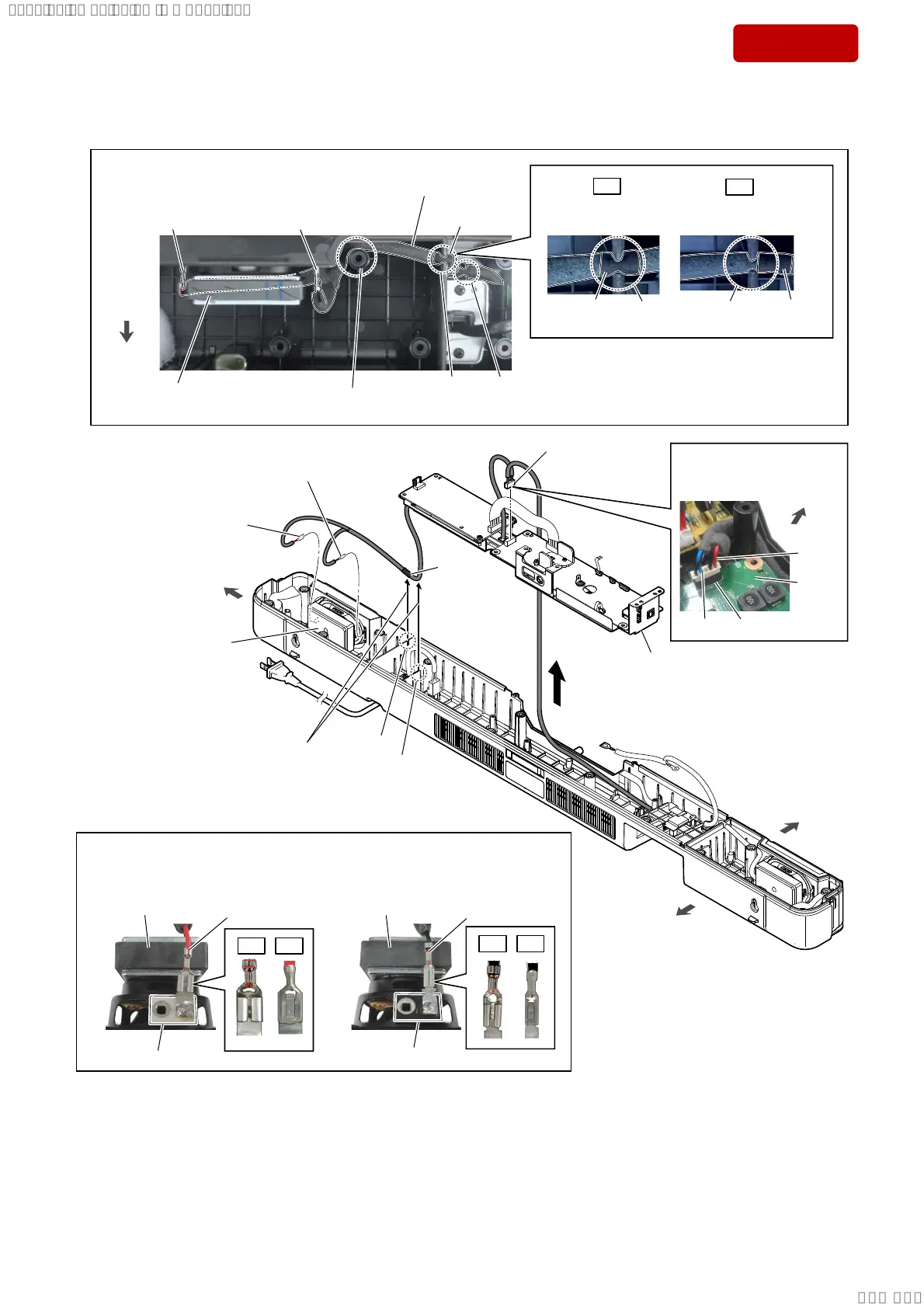
2-12. CHASSIS BLOCK-2
• Continued on 2-13 (page 20).
tape
portion
(See Fig. H)
6SHDNHUFDEOHVHWWLQJ
groove
3 terminal (wide)
[red]
3 terminal (narrow)
[black]
1
Lift up the chassis block
in
the direction of the arrow.
2 Draw the speaker cable
out of the two grooves.
speaker unit
(for R-ch)
front side
rear side
right side
4 speaker cable
connector (CN3)
(See Fig. H)
,QVWDOODWLRQGLUHFWLRQIRUWKHWHUPLQDORIVSHDNHUFDEOHIRU5FK
Note:
When connecting the terminals of the speaker cable to the speaker unit (for R-ch),
be careful of the direction of the terminals.
)LJ+!
rear side
–7RSYLHZ–
speaker cable
terminal (wide)
[red]
terminal (narrow)
[black]
groove groove
speaker unit
(for R-ch)
–7RSYLHZ–
,QVWDOODWLRQGLUHFWLRQIRU
WKHFRQQHFWRU&1
MAIN
board
[red]
[blue]
connector (CN3)
front side
Pass the speaker cable
beside the screw boss.
terminal (wide)
[red]
terminal [black]
terminal [white]
terminal (narrow)
[black]
speaker unit (for R-ch) speaker unit (for R-ch)
OK 1*
OK 1*
tape portion
OK
1*
tape
portion
tape
portion
groove
groove
Tape portion is not
in the groove.
Tape portion is
in the groove.
chassis block
groove
SYSSET
2019/02/1301:27:25(GMT+09:00)