HT-S350/SD35
21
Sony CONFIDENTIAL
For Authorized Servicer
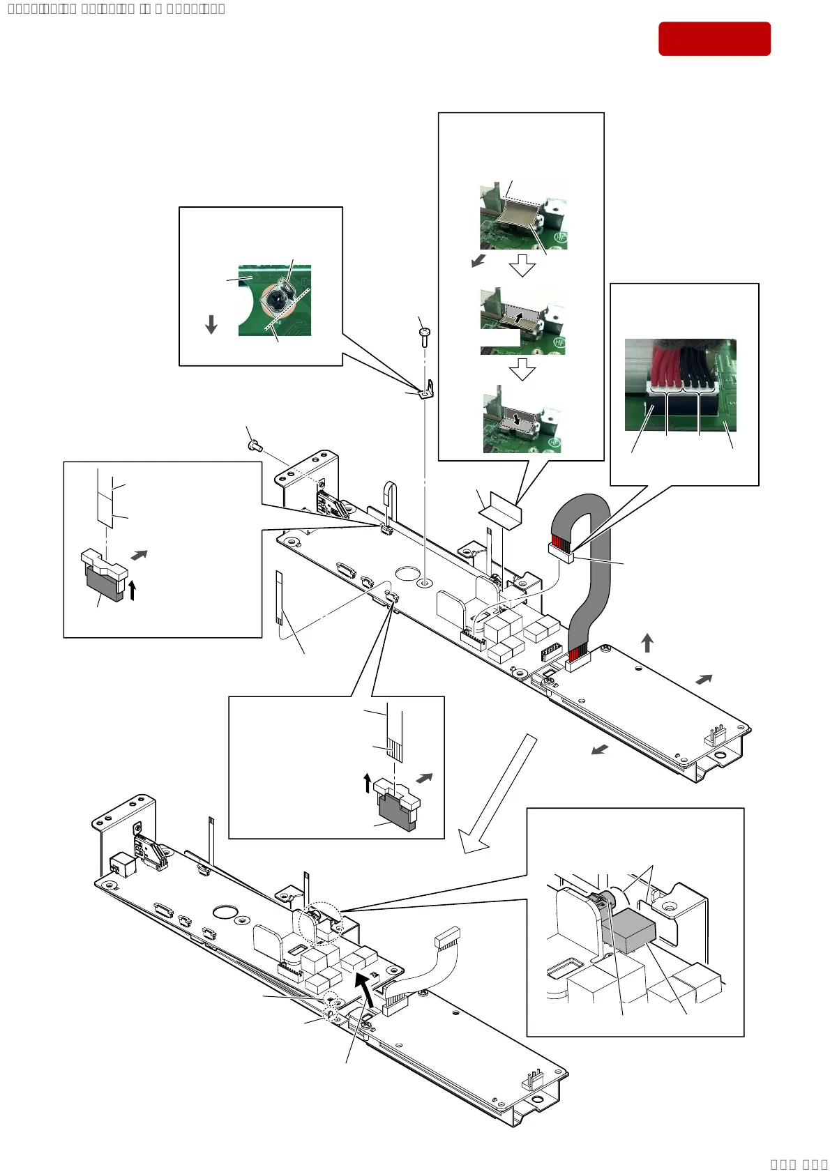
2-14. MAIN BOARD-1
• Continued on 2-15 (page 22).
8 screw (B3 u 6)
Note:
When tightening screw, tighten
the below torque value.
tightening torque:
. . 1P
9 screw
(BTP3 u 10)
1
Unlock the
connector.
connector (CN5)
terminal side
2 Draw the FFC (6 core)
out of the connector.
4
Unlock the
connector.
connector
(CN7)
terminal side
5 Draw the FFC (6 core)
out of the connector.
front side
rear side
top side
rear
side
3 FFC (6 core)
(L=40 mm)
rear side
6 connector
(CN1)
7 conductive
tape
qa
Lift up the MAIN board
in
the direction of the arrow.
qs rib
hole
two holes
qd Draw the connector and jack
out of the two holes.
jack
connector
0 terminal
,QVWDOODWLRQGLUHFWLRQIRU
WKHFRQQHFWRU&1
–)URQWYLHZ–
MAIN
board
[red] [black]
connector
(CN1)
guide line
conductive
tape
front side
$IIL[LQJWKHFRQGXFWLYHWDSH
,QVWDOODWLRQGLUHFWLRQ
IRUWKHWHUPLQDO
MAIN
board
terminal
guide line
front side
1 Paste the conductive tape
according to the guide line.
2 Press.
3 Press.
SYSSET
2019/02/1301:27:25(GMT+09:00)