SA-WS350/WSD35
12
Sony CONFIDENTIAL
For Authorized Servicer
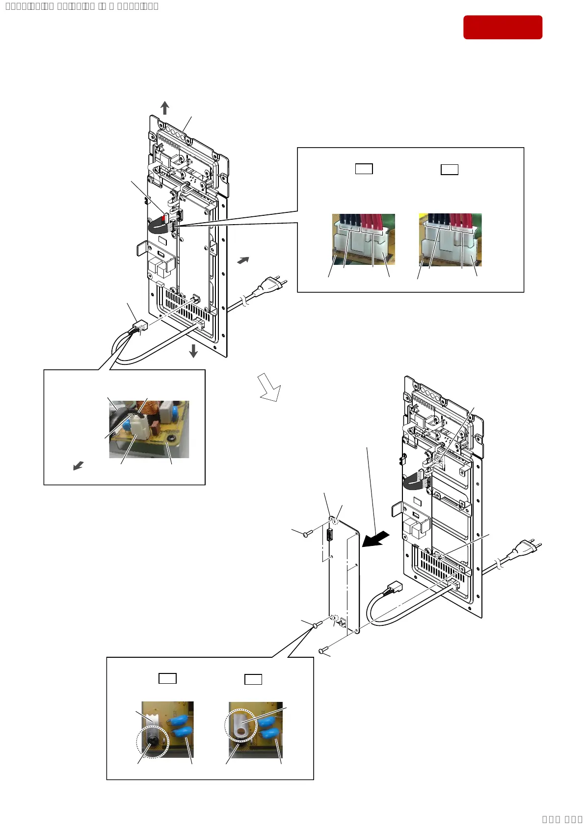
2-5. POWER BOARD
$&FRUGVHWWLQJ
1RWHIRULQVWDOOLQJWKHVFUHZ
+RZWRLQVWDOOWKH63.FRUGSRZHUFDEOHFRQQHFWRU&1
rear side
top side
AMP block
1 AC cord connector (CN1)
2 SPK cord power cable
connector (CN2)
4 Remove the POWER board
in the direction of the arrow.
claw
side
bottom side
3 two screws
(BVTP3 u 8)
3 screw
(BVTP3 u 8)
3 three screws
(BVTP3 u 8)
hole
hole
5 POWER board
Note:
When installing the POWER board,
align the two ribs and two holes.
rib
rib
POWER board
claw side
AC cord
bottom side
2.
1*
GND plate is screwed.
GND plate is floating.
GND
plate
screw
screw
GND
plate
POWER board
POWER board
US, CND: Black
AEP, UK: Brown
US, CND: White
AEP, UK: Blue
2.
1*
SPK cord power
cable connecter
is fully inserted.
SPK cord power
cable connecter
is not fully inserted.
–/HIWYLHZ––/HIWYLHZ–
POWER board
CN2
[black] [red]
CN2
POWER board
[black]
[red]
SYSSET
2019/02/1301:37:00(GMT+09:00)