44
HT-S350/SD35
Sony CONFIDENTIAL
For Authorized Servicer
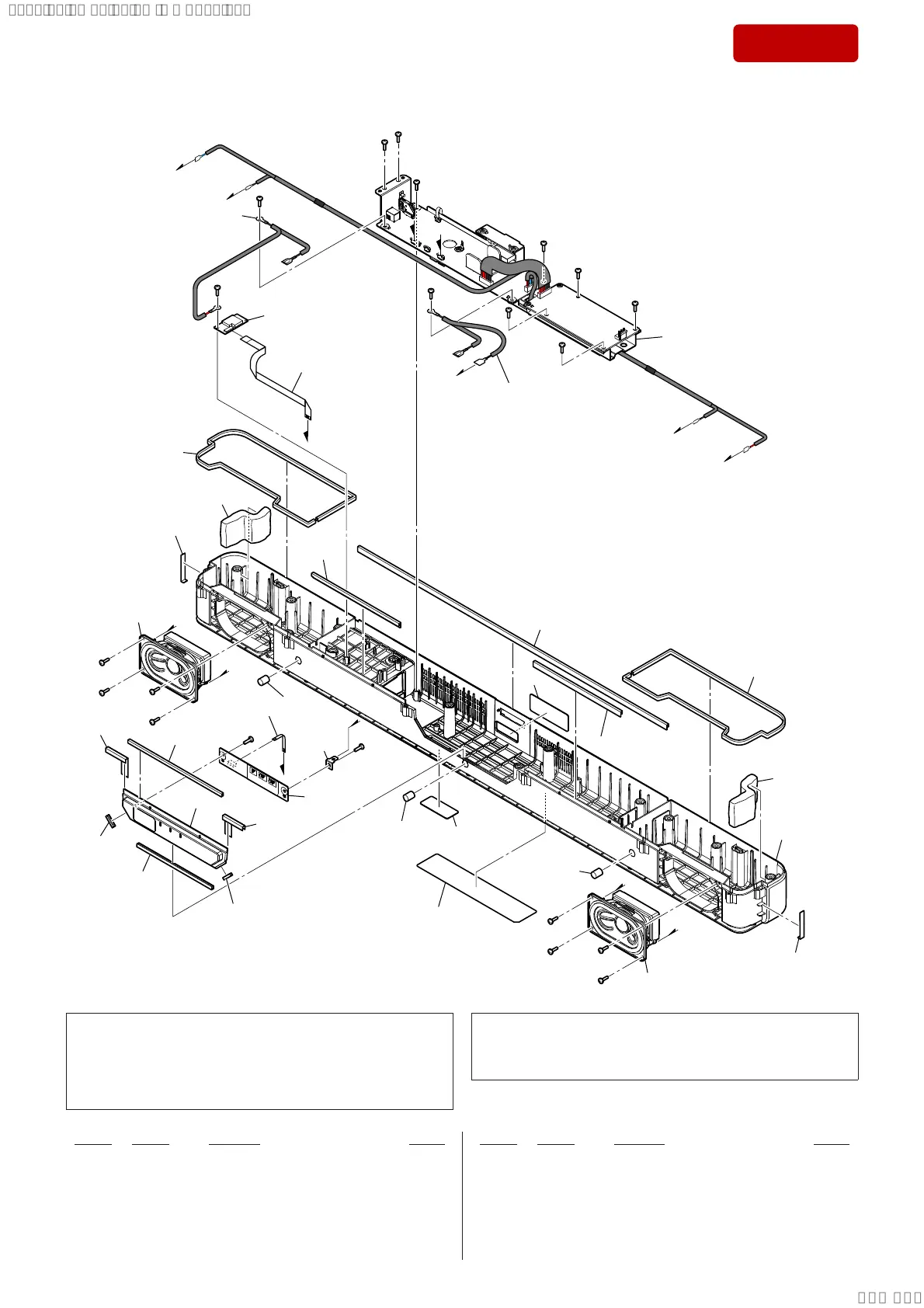
5-3. BOTTOM CASE SECTION
not supplied
not supplied
not supplied
not supplied
not supplied
not supplied
not supplied
not supplied
not supplied
not supplied
not supplied
not
supplied
102
#1
not supplied
J
#1
#1
#1
#1
#1
#1
I
H
#1
#1
#1
#1
not supplied
I
FFC1
(See Note 2)
BT1
(See Note 1)
H
#1
#1
FFC4
(See Note 2)
not supplied
101
not supplied
not supplied
not supplied
not
supplied
not
supplied
not
supplied
not
supplied
not
supplied
not
supplied
J
D
E
#1
#1
#1
#1
SP1
F
G
#1
#1
#1
#1
SP2
not supplied
(model number label)
F
G
chassis section
D
E
Note 1: If BT module (Ref. No. BT1) is replaced with a new part, refer to
“RESET METHOD” on page 6, be sure to perform the reset.
Also, after completing the reset, refer to “WIRELESS CONNEC-
TION (LINK) WORK OF BAR SPEAKER AND THE SUB-
WOOFER” on page 7, perform the wireless connection of bar
speaker and subwoofer.
Note 2: As for FFC KIT (CA1_BAR), all fl exible fl at cables (Ref. No.
FFC1, FFC2, FFC3, FFC4) will be 1 set. If FFC KIT (CA1_BAR)
is replaced, install it after bending it in the same form as that be-
fore replacement.
101 930100036 LED BOARD, COMPLETE (with Cushion)
102 930100052 PC SHEET (USB)
BT1 930100039 BT MODULE (CA1 BAR) (See Note 1)
FFC1 930100063 FFC KIT (CA1_BAR) (18 core, L = 168.5 mm)
(See Note 2)
FFC4 930100063 FFC KIT (CA1_BAR) (6 core, L = 40 mm)
(See Note 2)
SP1 930100038 SPEAKER UNIT (CA1_BAR) (for L-ch)
SP2 930100038 SPEAKER UNIT (CA1_BAR) (for R-ch)
#1 768554719 SCREW +BTP 3X10 TYPE2 N-S
Ref. No. Part No. Description Remark Ref. No. Part No. Description Remark
SYSSET
2019/02/1301:27:25(GMT+09:00)