HT-S350/SD35
22
Sony CONFIDENTIAL
For Authorized Servicer
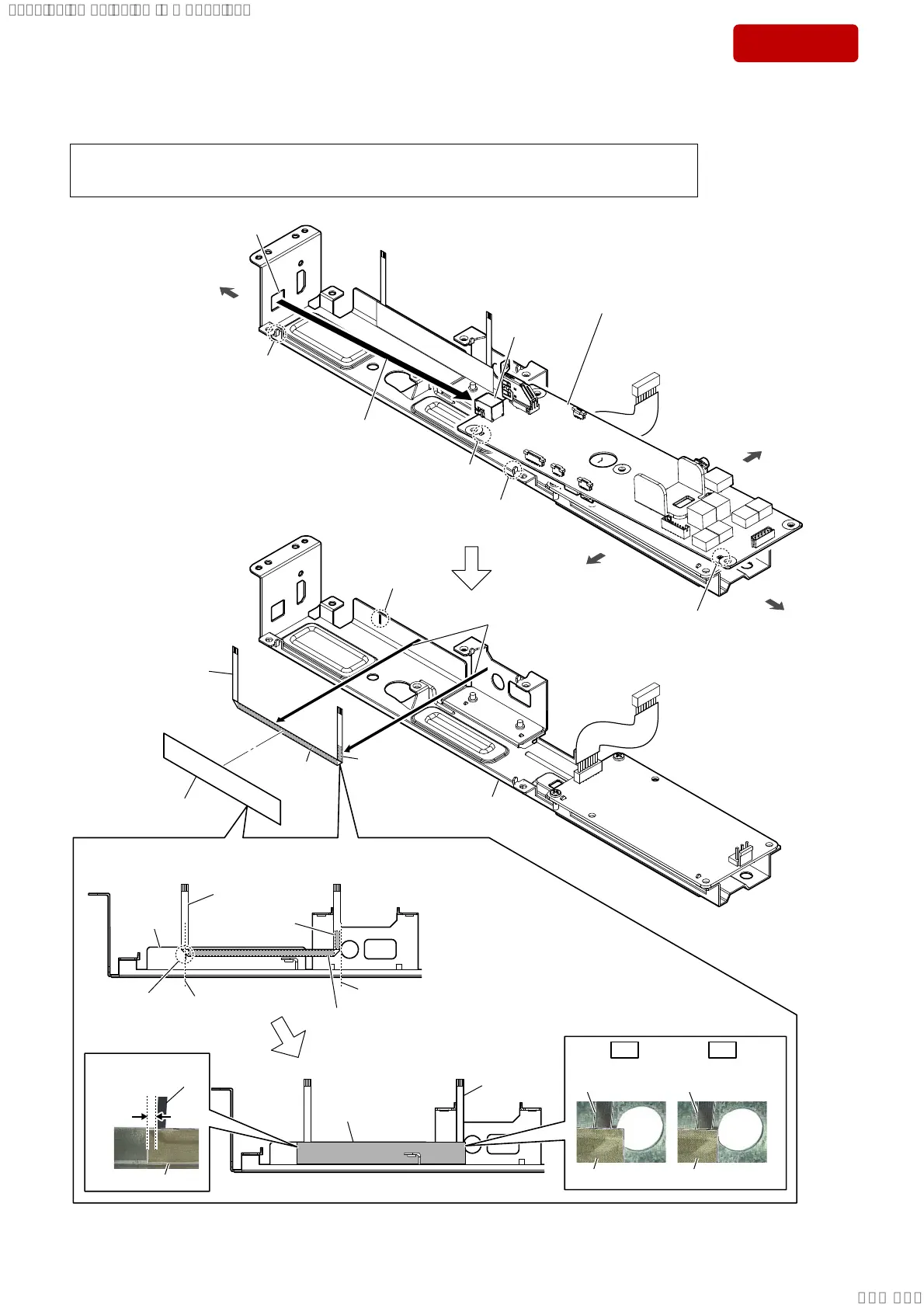
2-15. MAIN BOARD-2, FFC (6 CORE) (L=161 mm)
1 rib
hole
hole
2 Draw the connector
out of the hole.
connector
3 MAIN board
(See Note 1)
Note 2:
When installing the MAIN board,
align the two ribs and two holes.
hole
rib
))&FRUH/ PPVHWWLQJ
FFC (6 core)
(L=161 mm)
FFC (6 core)
(L=161 mm)
–)URQWYLHZ–
front side
rear side
left side
right side
metal
chassis
guide line
(center)
guide line
adhesive sheet
adhesive sheet
5 Peel the FFC (6 core) off
of the metal chassis.
6 FFC (6 core)
(L=161 mm)
metal chassis
Note 1:
If MAIN board is replaced with a new part, refer to “RESET METHOD” on page 6, be sure to perform the reset.
Also, after completing the reset, refer to “WIRELESS CONNECTION (LINK) WORK OF BAR SPEAKER AND
THE SUBWOOFER” on page 7, perform the wireless connection of bar speaker and subwoofer.
adhesive
sheet
adhesive
sheet
alignment mark
alignment mark
4 conductive tape
conductive
tape
conductive tape
5 ± 2 mm
FFC (6 core)
(L=161 mm)
FFC (6 core)
(L=161 mm)
OK OK
conductive tape conductive tape
–)URQWYLHZ–
FFC (6 core)
(L=161 mm)
SYSSET
2019/02/1301:27:25(GMT+09:00)