45
HT-S350/SD35
Sony CONFIDENTIAL
For Authorized Servicer
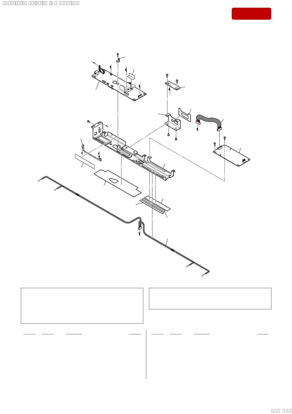
5-4. CHASSIS SECTION
not supplied
not supplied
not supplied
not supplied
not supplied
not supplied
not supplied
not supplied
#2
#2
FFC2
(See Note 2)
K
O
O
K
L
L
M
#2
#1
#1
#1
#1
#1
not supplied
not supplied
152
153
not supplied
N
N
151
(See Note 1)
M
not supplied
Note 1: If complete MAIN board (Ref. No. 151) is replaced with a new
part, refer to “RESET METHOD” on page 6, be sure to perform
the reset.
Also, after completing the reset, refer to “WIRELESS CONNEC-
TION (LINK) WORK OF BAR SPEAKER AND THE SUB-
WOOFER” on page 7, perform the wireless connection of bar
speaker and subwoofer.
Note 2: As for FFC KIT (CA1_BAR), all fl exible fl at cables (Ref. No.
FFC1, FFC2, FFC3, FFC4) will be 1 set. If FFC KIT (CA1_BAR)
is replaced, install it after bending it in the same form as that be-
fore replacement.
151 930100058 MAIN BOARD, COMPLETE (Including Heat sink)
(SA-S350: US, CND) (See Note 1)
151 930100059 MAIN BOARD, COMPLETE (Including Heat sink)
(SA-S350: AEP, UK) (See Note 1)
151 930100135 MAIN BOARD, COMPLETE (Including Heat sink)
(SA-SD35: US) (See Note 1)
151 930100144 MAIN BOARD, COMPLETE (Including Heat sink)
(SA-SD35: AEP, UK) (See Note 1)
152 930100053 IR RP BOARD, COMPLETE
0 153 930100054 POWER BOARD, COMPLETE
(SA-S350: US, CND/SA-SD35: US)
0 153 930100055 POWER BOARD, COMPLETE
(SA-S350: AEP, UK/SA-SD35: AEP, UK)
FFC2 930100063 FFC KIT (CA1_BAR) (6 core, L = 161 mm)
(See Note 2)
#1 768554719 SCREW +BTP 3X10 TYPE2 N-S
#2 768254709 SCREW +B 3X6
Ref. No. Part No. Description Remark Ref. No. Part No. Description Remark
SYSSET
2019/02/1301:27:25(GMT+09:00)