HT-S350/SD35
17
Sony CONFIDENTIAL
For Authorized Servicer
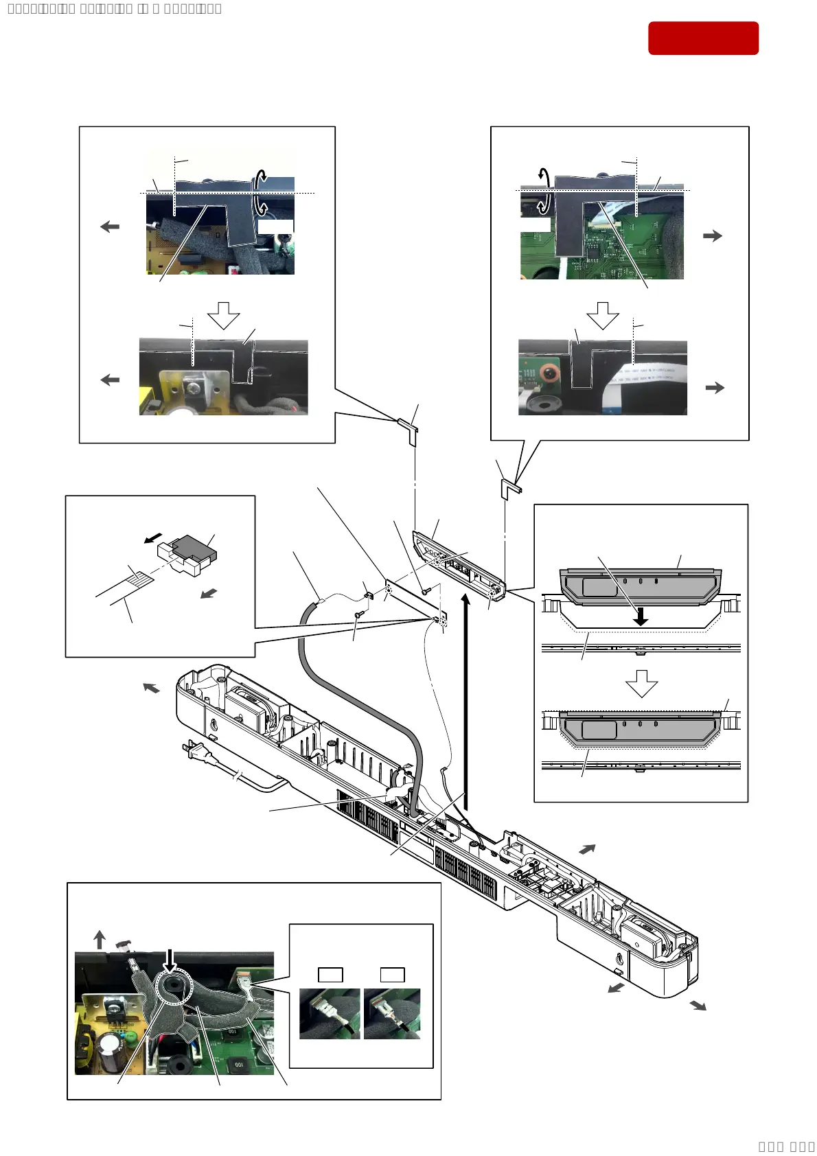
2-10. LED BOARD
front side
rear side
left side
right side
6 screw
(BTP3 u 10)
5
Lift up the panel LED block
in the direction of the arrow.
hole
boss
hole
boss
6 screw
(BTP3 u 10)
9 LED board
Note:
When installing the LED board,
align the two bosses and two holes.
8
panel LED
assy
+RZWRLQVWDOOWKHSDQHO/('EORFN
Insert straight into
the interior.
groove
groove
panel LED block
–)URQWYLHZ–
Flat.
3 wire with
terminal
(See Fig. D)
4
cushion
4
cushion
$IIL[LQJWKHFXVKLRQ
cushion
guide line
(center)
–7RSYLHZ–
–,QQHUYLHZ–
guide line
(center)
guide line
guide line
guide line
right side
right side
cushion
$IIL[LQJWKHFXVKLRQ
–7RSYLHZ–
–,QQHUYLHZ–
left side
left side
cushion
7 terminal
Bend.
Bend.
guide line
1
Unlock the
connector.
connector
(CN1)
terminal side
rear side
2 Draw the FFC (6 core)
out of the connector.
OK NG
cushion
Bend.
Bend.
)LJ'!
:LUHVHWWLQJ
,QVWDOODWLRQGLUHFWLRQ
IRUWKHWHUPLQDO
SPK cord power
wire with terminal
screw boss
Push the SPK cord power.
front side
–7RSYLHZ–
SPK cord power
(See Fig. D)
SYSSET
2019/02/1301:27:25(GMT+09:00)