SA-WS350/WSD35
8
Sony CONFIDENTIAL
For Authorized Servicer
SECTION 2
DISASSEMBLY
• This set can be disassembled in the order shown below.
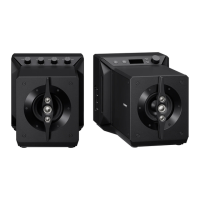
2-1. DISASSEMBLY FLOW
SET
2-4. MAIN BOARD
(Page 11)
2-5. POWER BOARD
(Page 12)
2-6. KEY BOARD, BUTTON
(Page 13)
2-7. MINI JACK BOARD
(Page 14)
2-8. BT MODULE (SW)
(Page 15)
2-2. AMP BLOCK
(Page 9)
2-3. AC CORD
(Page 10)
2-11. SPEAKER UNIT (CA1_SW)
(Page 18)
2-10. LED BOARD, FRONT PANEL ASSY (CA1_SW)
(Page 17)
2-9. FFC CABLE (6 CORE),
FFC CABLE (12 CORE)
(Page 16)
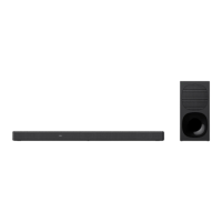
JIG
When disassembling the unit, use the following
jig for speaker removal.
Part No. Description
J-2501-238-A JIG FOR SPEAKER REMOVAL
SYSSET
2019/02/1301:37:00(GMT+09:00)