Installation and set-up manual 208668 43
CRANEX Novus e 4. Checking the alignment and fi nishing the installation
5. PC: Use the measuring tools in the dental
imaging software to examine the dimensions
of the balls that appear on the image. Magnify
the image so that you can accurately measure
the dimensions.
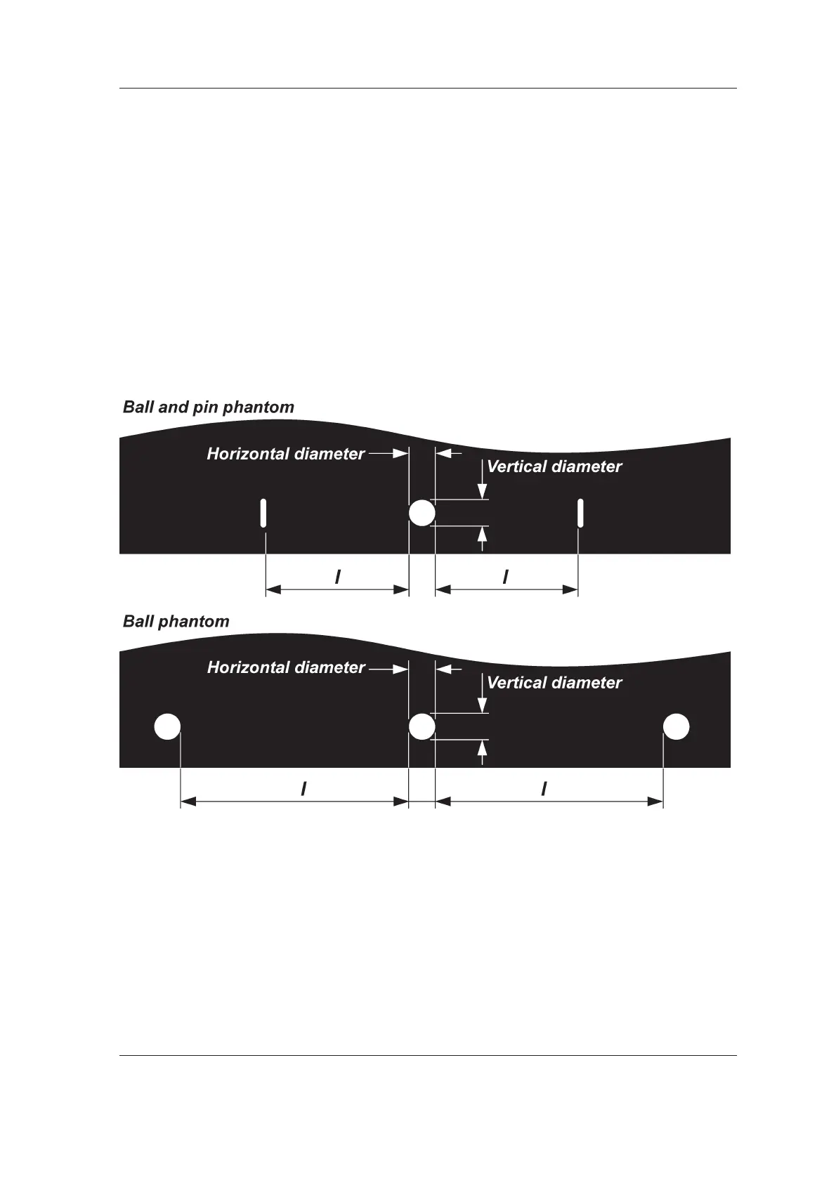
If the image geometry is correct, the center
ball will be round with a difference of no more
than 0.2 mm between the horizontal diameter
and the vertical diameter.
Also the distances (l) from the side of the
center ball to the sides of the balls (ball
phantom) or from the side of the center ball to
the sides of the pins (ball and pin phantom)
must be equal with a difference of no more
than 1.0 mm between the two distances.
If the center ball is NOT ROUND and/or the
distances (l) between the pins or balls are
NOT WITHIN THE TOLERANCE, then the
rotating unit (RU) or the chin rest must be
adjusted.
See 5.3 Adjusting the image geometry.
IMPORTANT NOTE:
In some cases you may have to adjust the
position of both the rotating unit AND the chin
rest.