SPEKTRUM DX7 • INTRODUCTION
SPEKTRUM DX7 • INTRODUCTION
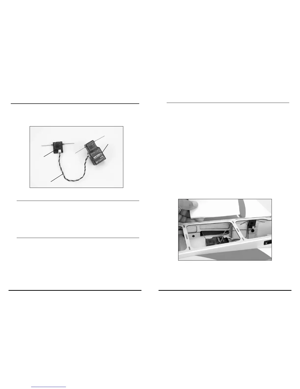
Receiver Installation
Install the main receiver using the same method you would use to install a conventional receiver in your aircraft.
Typically, wrap the main receiver in protective foam and fasten it in place using rubber bands or hook and loop
straps. Alternately, in electric models or helicopters, it’s acceptable to use thick double-sided foam tape to fasten
the main receiver in place.
Antenna Polarization
For optimum RF link performance it’s important that the remote antennas be mounted in an orientation that
allows for the best possible signal reception when the aircraft is at all possible attitudes and positions. This
is known as antenna polarization. If two receivers are used, the antennas should be oriented perpendicular
to each other, typically one vertical and one horizontal. This allows the greatest exposed visual cross section
of the antennas from all aircraft orientations. If three antennas are used it is recommended that one antenna
be mounted vertically, one horizontally in-line with the fuselage and one horizontally perpendicular to the
fuselage. This covers the X,Y and Z axis offering superb cross section visibility in all aircraft orientations. An
optional fourth antenna can be added at an intermediate angle offering even greater RF link security and system
redundancy.
Mounting the remote receiver in a slightly different location, even just inches away from the primary receiver,
gives tremendous improvements in path diversity. Essentially, each receiver sees a different RF environment and
this is key to maintaining a solid RF link, even in aircraft that have substantial conductive materials (e.g., larger
gas engines, carbon fiber, pipes, etc.), which can weaken the signal.
Using servo tape, mount the remote receiver keeping the remote antennas at least 2 inches away from the
primary antenna. Ideally, the antennas will be oriented perpendicularly to each other, however, we’ve found this
to not be critical. In airplanes, we’ve found it best to mount the primary receiver in the center of the fuselage on
the servo tray and to mount the remote receiver to the side of the fuselage or in the turtle deck.
SPEKTRUM DX7 • INTRODUCTION
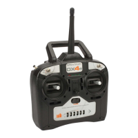
Receiver and Servo Installation
The AR7000 incorporates dual receivers, offering the security of dual path RF redundancy. An internal
receiver is located on the main PC board, while a second external receiver is attached to the main board
with a 6-inch extension. By locating these receivers in slightly different locations in the aircraft, each receiver
is exposed to its own RF environment, greatly improving path diversity (the ability for the receiver to see the
signal in all conditions).
QuickConnect
™
and Brownout Alert
The remote receivers now included with the AR7000 feature QuickConnect with Brownout Detection. Should
a power interruption occur (brownout), the system will reconnect immediately when power is restored and the
LEDs on each connected receiver will flash indicating a brownout (power interruption) has occurred. Brownouts
can be caused by an inadequate power supply (weak battery or regulator), a loose connector, a bad switch, an
inadequate BEC when using an electronic speed controller, etc. Brownouts occur when the receiver voltage
drops below 3.2 volts thus interrupting control as the servos and receiver require a minimum of 3.2 volts to
operate.
How Brownout Detection Work
When the receiver voltage drops below 3.2 volts the system drops out (ceases to operate). When power is
restored, the receivers will immediately attempt to reconnect to the last two frequencies they were connected to.
If the two frequencies are present (the transmitter was left on) the system reconnects typically in about 4ms. The
receivers will then blink indicating a brownout has occurred. If at any time the receiver is turned off then back on
and the transmitter is not turned off, the receivers will blink as a power interruption was induced by turning off
the power to the receiver. In fact this simple test (turning off then on the receiver) will allow you to determine if
your system’s brownout detection is functioning.
Note: If a brownout occurs in-flight it is vital that the cause of the brownout be determined and
corrected. QuickConnect and Brownout Detection are designed to allow you to safely fly through
most short duration power interruptions. However, the root cause of these interruptions must be
corrected before the next flight to prevent catastrophic safety issues.
External Receiver
6” Extension
Main Receiver

 Loading...