Installation and Reference Manual
Installing a System
Installation and Reference Manual v3.2/0410/6 23
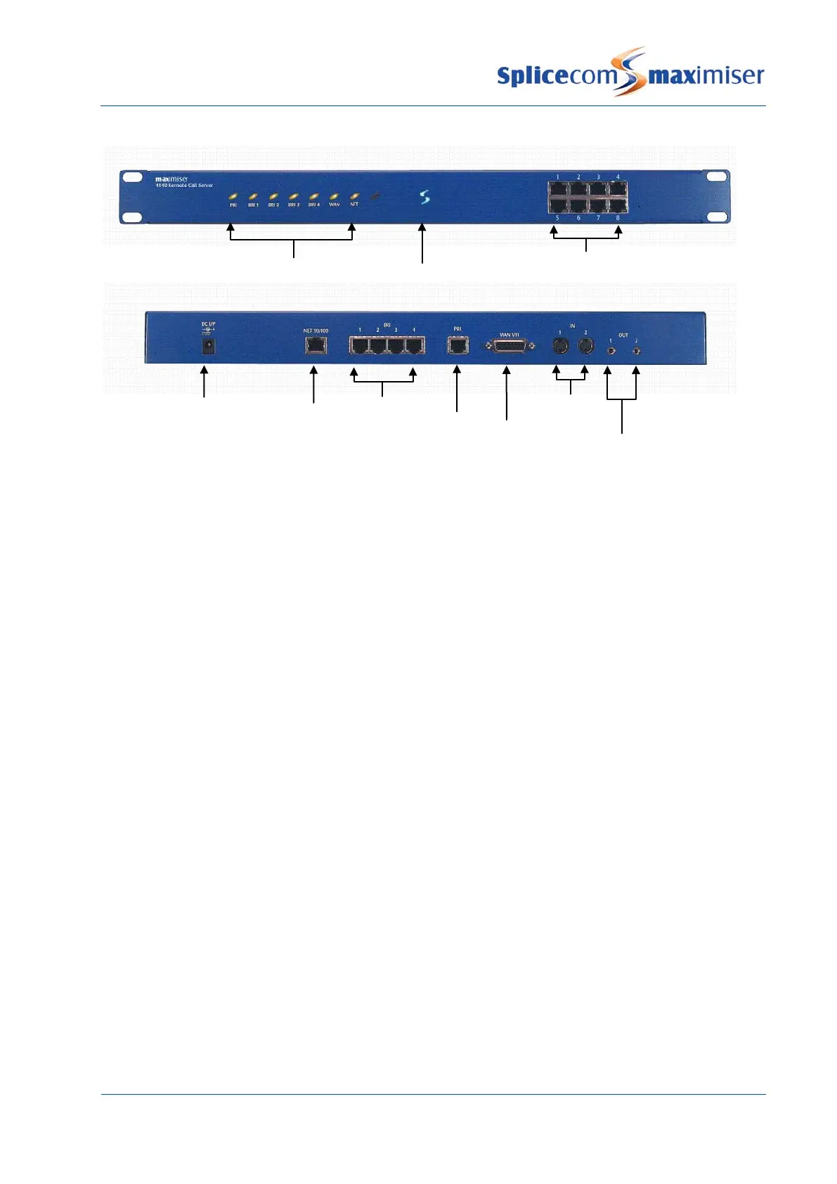
4140 Remote Call Server – Front and Rear view
Once the Call Server has been powered up the following should be noted:
• If the Call Server’s DHCP Server functionality has been enabled the Call Server will give out an address
range of 192.168.0.2 to 192.168.0.250, with 192.168.0.250 being the first address given out. (For
further information on using DHCP please refer to page 29 for further details.)
• When connecting to the LAN ports on the front of the 5100, 5108 or 4100 Call Server straight or
crossover cables can be used because each port automatically changes to MDI/MDX. When
connecting to the LAN port at the back of the 4140 Remote Call Server a crossover cable is required.
• The ISDN Trunk ports available on a Call Server can be used to connect to the exchange or to another
system. Please refer to page 159 for further information.
• The system operates in native mode at G.711 64k with echo cancellation. If the
imiser system is
connected to the company LAN and that LAN is used to carry voice then that LAN must provide Quality
of Service via LAN switches.
• The 5100 and 5108 Call Server and the 4140 Remote Call Server provide 16/4/8 analogue extension
ports respectively. When either of these Call Servers is the first to be installed each port will be
automatically assigned to a User named Extn2001, Extn2002 etc and given an extension numbers of
2001, 2002 etc. Please refer to page 48 for further information on using an analogue extension port.
• Please note that the first 8 analogue ports on the 5100 Call Server are activated, the remaining 8 ports
will require a POTS licence to activate each port. Please refer to page 35 for further information on
Licensing.
LED status lights
Ethernet LAN port
(for future use)