BER Test panel UM1811
38/52 DocID026814 Rev 1
8 BER Test panel
The “Bit Error Rate” (BER) Test panel may be used to automate the evaluation of the bit
error rate.
8.1 Typical setup
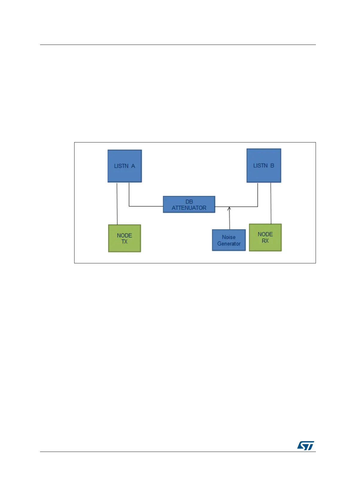
The following diagram shows the typical environment to perform the BER Test.
Figure 24. BER Test setup
The BER may be checked in different conditions. Increasing or decreasing the level of
transmission attenuation and the level of injected noise results in a different BER value at
the receiver side. The nature of the interfering noise (AWGN, colored, single carrier, etc.)
may also impact the BER performance.
8.2 Test description
To be able to perform the BER Test, two G3-PLC platforms need be connected to the G3-
PLC GUI. Both boards need to be configured in the PHY operational mode as described in
Section 5 on page 17. The user needs to configure one G3-PLC platform in the TX mode
and the other one in the RX mode.
The user can then follow the steps described in Section 10.3 on page 43 in order to correctly
configure the nodes.
Once the nodes configuration is done, the user can open the Test panel, as explained in
Figure 25:
Click on the Plugin Settings icon in the menu bar (1)
Enable the TESTLAB panel (2)
The TESTLAB panel will appear at the right side of the tool.