131/317
5-Peripherals
The resynchronization is the most difficult thing. It uses a clock a 16 times the bit rate, and the
state of the receive data pin is checked at each period of that clock. When a falling edge is de-
tected, a mechanism takes that time plus half a bit period as the reference time for the sam-
pling of all subsequent bits. The start bit is also checked to be a zero at the sampling time. It
is not, it is considered a false start bit. The NF bit is set in the SCISR, and the receiving se-
quence is not initiated. All successive bits are shifted into the receive shift register. When the
stopbitarrives,itisalsocheckedforaone.Ifitisazero,theFEbitissetintheSCISR.The
RDRF bit is set when the reception is complete. It can generate an interrupt, so that the re-
ceived character may be picked up.
05-sci2
Receiver
baud rate
generator
f
cpu
Bit
rate
16xBit
rate
Start bit
detection
Good
start bit
ON
Stop876543210
OFF
Receive
counter: 1/9 if M=0
1/10 if M=1
R8 M
SCICR1
only if M=1
1=9 bits
0=8 bits
Bad
start bit
Internal data bus
RDI
RDRF IDLE OR NF FE
SCISR
RDR
Receive shift register
1ifbad
stop bit
1ifRDRF=1
while a good
start bit occurs
Receive
control
I
RIE ILIE RE
SCICR2
CCR
Interrupt to
the core
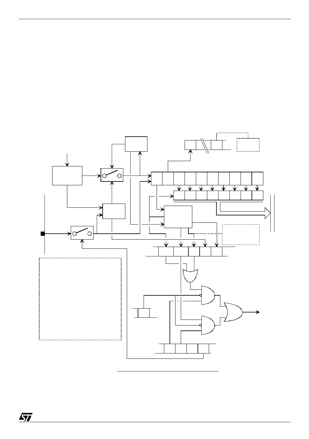
SCI simplified receive bock diagram
R8:Receive data bit 8
M: Word length
RDRF: Receive data ready flag
IDLE: Idle line detect
OR: Overrun error
NF: Noise flag
FE: Framing error
RIE: Receiver interrupt enable
ILIE: Idle line interrupt enable
RE: Receiver enable