DocID15067 Rev 3 13/49
AN2834 ADC errors
48
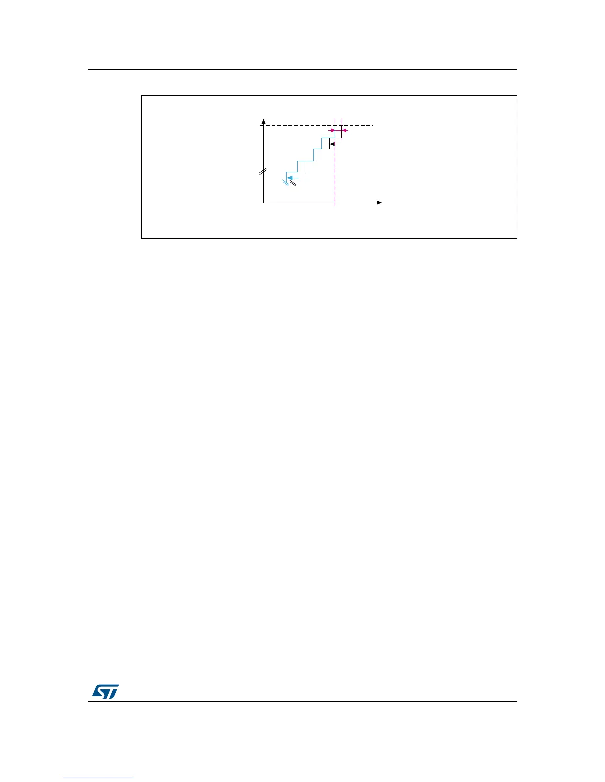
Figure 10. Negative gain error representation
1. The gain error, E
G
, is shown in magenta.
2.1.3 Differential linearity error
The differential linearity error (DLE) is the maximum deviation between the actual and ideal
steps. Here ‘ideal’ does not refer to the ideal transfer curve but to the ADC resolution. The
DLE is denoted by E
D
. It is represented in Figure 11.
E
D
= Actual step width – 1 LSB
Ideally, an analog input voltage change of 1 LSB should cause a change in the digital code.
If a
n analog input voltage greater than 1 LSB is required for a change in digital code, a
di
fferential linearity error is observed. The DLE therefore corresponds to the maximum
additional voltage that is required to change from one digital code to the next.
The DLE is also known as the differential non-linearity (DNL) error.
Example
A given digital output should correspond to an analog input range. Ideally, the step width
should be 1 LSB. Let us assume that the digital output is the same over an analog input
volta
ge range of 1.9998 V to 2.0014 V, the step width will be:
2.0014 V – 1.9998 V = 1.6 mV.
E
D
is thus the voltage difference between the higher (2.0014 V) and the lower (1.9998 V)
analog voltages minus the voltage corresponding to 1 LSB.

 Loading...


