How to get the best ADC accuracy AN2834
42/49 DocID15067 Rev 3
Workaround for extra high impedance sources
This workaround combines both hardware and software changes.
Hardware change
The hardware change consists in adding a large external capacitor (C
ext
) to the input pin.
The capacity size connected to the input pin must reach the value that causes the
discharging of the internal sampling capacity C
sh
to the external capacitor C
ext
without
increasing the voltage on C
ext
to more than 0.5 LSB.
Example
If the internal capacitor (C
sh
= 16 pF) is charged to full scale (U
max
, which corresponds to
4096 LSB), then the external capacitor C
ext
must be charged at maximum 0.5 LSB voltage
level (U
lsb
) after discharging C
sh
to it. The capacity of C
ext
will then be:
The closest larger standard value chosen here is: C
ext
= 150 nF.
If the internal sampling capacitor C
sh
is not charged to full voltage range (4096 level) before
sampling, the C
ext
value can be computed by replacing “4096” in the formula above.
Calculating with 4096 level gives precise measurement results also in the case of ADC input
channels switching (C
sh
was charged from different ADC input in the previous
measurement).
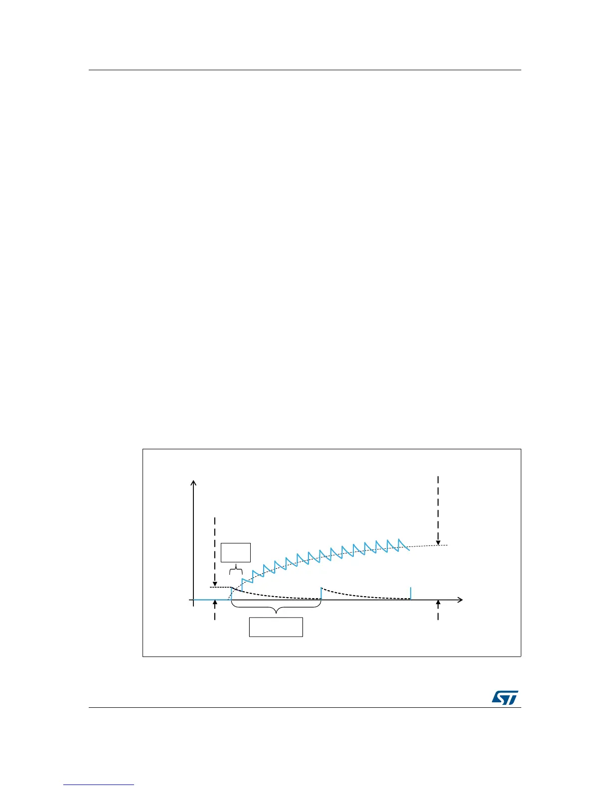
A side effect of this hardware
workaround is the cyclical charging of C
ext
which must be
taken into account. Each ADC conversion transfers charge from C
sh
to C
ext
. One transfer
charges the C
ext
below 0.5 LSB, as described above, but more transfers can charge C
ext
to
larger values if it is not discharged between two conversions. Figure 36 shows an example
of this scenario where the ADC measurement is performed faster.
Figure 36. Charging the external capacitor with too short time between conversions

 Loading...


