How to get the best ADC accuracy AN2834
26/49 DocID15067 Rev 3
3.2.5 Matching the ADC dynamic range to the maximum signal amplitude
This method improves accuracy by a proper selection of the reference voltage or by using a
preamplifier stage to obtain the maximum possible resolution using the full ADC output
range.
Selecting a reference voltage (method for devices delivered in 100-/144-pin
packages only)
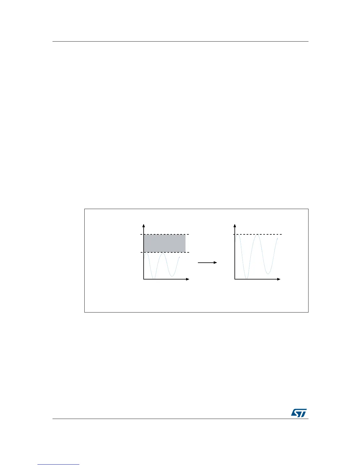
The reference voltage is selected in the expected range of the signal to be measured. If the
measured signal has an offset, then the reference voltage should also have a similar offset.
If the measured signal has a defined maximum amplitude, then the reference voltage should
also have a similar maximum value. By matching this reference voltage to the measurement
signal range, we obtain the maximum possible resolution using the full ADC output range.
In STM32 microcontrollers delivered in 100- and 144-pin packages, the ADC reference
volta
ge is connected to the external V
REF+
and V
REF-
pins that should be tied to ground.
This makes it possible to match the reference voltage and the measured signal range.
For example, if the measured signal varies between 0 V and 2.5 V, it is recommended to
choose a V
REF+
of 2.5 V, possibly using a reference voltage like LM235 (see LM235
datasheet for more details). Figure 23 illustrates these conditions.
Note: The voltage on V
REF+
may range between 2.4 V and V
DDA
.
Figure 23. Selecting the reference voltage
Using a preamplifier
If the measured signal is too small (in comparison with the ADC range), then an external
preamplifier can be useful. This method can be implemented whatever the STM32 package,
and more specifically in packages that do not have a V
REF+
input.
For example, if the measured signal varies between 0 V to 1 V and V
DDA
is set to 3 V, the
signal can be amplified so that its peak-to-peak amplitude is similar to the V
DDA
value. The
gain is then equal to 3 (see Figure 24 for an example).

 Loading...


