EasyManuals Logo

ST STM32 Application Note

ST STM32
49 pages
To Next Page IconTo Next Page
To Previous Page IconTo Previous Page
Page #15 background imageLoading...
Page #15 background image
DocID15067 Rev 3 15/49
AN2834 ADC errors
48
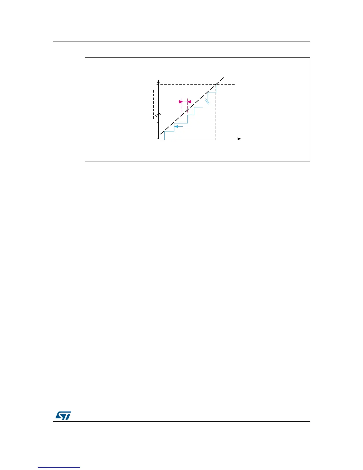
Figure 12. Integral linearity error representation
1. The integral linearity error, E
L
, is shown in magenta.
Example
If the first transition from 0 to 1 occurs at 550 µV and the last transition (0xFFE to 0xFFF)
occurs at 3.298435 V (gain error), then the line on the transfer curve that connects the
ac
tual digital codes 0x1 and 0xFFF is the endpoint correlation line.
DLE
'LJLWDORXWSXW
$FWXDOWUDQVIHUFXUYH
(
/

w9
9
9
$,1

Table of Contents

Other manuals for ST STM32

Questions and Answers:

Question and Answer IconNeed help?

Do you have a question about the ST STM32 and is the answer not in the manual?

ST STM32 Specifications

General IconGeneral
SeriesSTM32
CategoryMicrocontrollers
CoreARM Cortex-M0, Cortex-M0+, Cortex-M3, Cortex-M4, Cortex-M7, Cortex-M33
Clock SpeedUp to 480 MHz
GPIO PinsUp to 144
Communication InterfacesI2C, SPI, USART, USB, CAN, Ethernet
Package TypesLQFP, BGA, WLCSP
ADC Resolution12-bit, 16-bit (varies by series)
DAC Resolution12-bit (varies by series)
Operating Temperature-40°C to +85°C or +105°C

Related product manuals