EasyManuals Logo

ST STM32 Application Note

ST STM32
49 pages
To Next Page IconTo Next Page
To Previous Page IconTo Previous Page
Page #6 background imageLoading...
Page #6 background image
ADC internal principle AN2834
6/49 DocID15067 Rev 3
1 ADC internal principle
1.1 SAR ADC internal structure
The ADC embedded in STM32 microcontrollers uses the SAR (successive approximation
register) principle, by which the conversion is performed in several steps. The number of
conversion steps is equal to the number of bits in the ADC converter. Each step is driven by
the ADC clock. Each ADC clock produces one bit from result to output. The ADC internal
design is based on the switched-capacitor technique.
The following figures (Figure 1 to Figure 6) explain the principle of
ADC operation. The
example given below shows only the first steps of approximation but the process continues
till the LSB is reached.
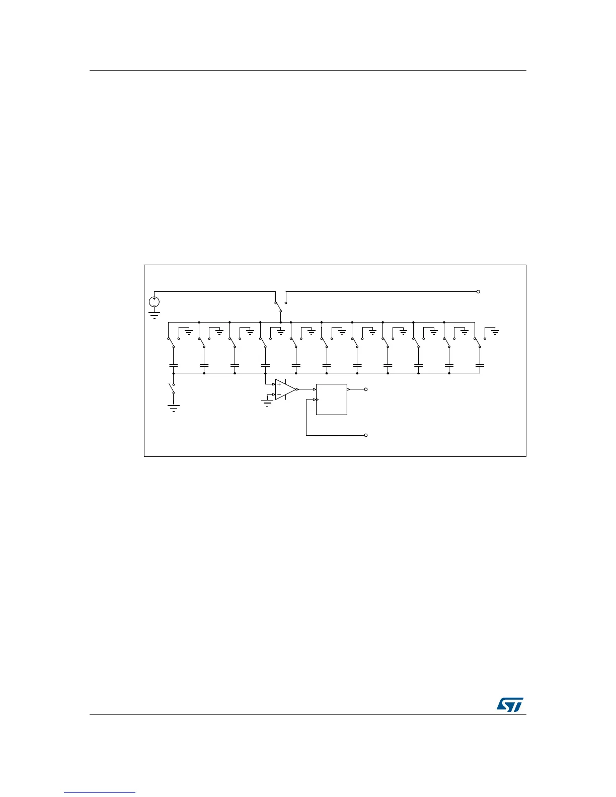
Figure 1. Basic schematic of SAR switched-capacitor ADC (example of 10-bit ADC)
1. Basic ADC schematic with digital output.
ĂŝϭϳϬϵϳď
6
6E
&/.
' 4
&/5
35
$
6
6D
9,1
$'&'DWD
$'&&ON
6 6 6 6 6 6 6
& & & & & & & & &
95()
6 6
& &

Table of Contents

Other manuals for ST STM32

Questions and Answers:

Question and Answer IconNeed help?

Do you have a question about the ST STM32 and is the answer not in the manual?

ST STM32 Specifications

General IconGeneral
SeriesSTM32
CategoryMicrocontrollers
CoreARM Cortex-M0, Cortex-M0+, Cortex-M3, Cortex-M4, Cortex-M7, Cortex-M33
Clock SpeedUp to 480 MHz
GPIO PinsUp to 144
Communication InterfacesI2C, SPI, USART, USB, CAN, Ethernet
Package TypesLQFP, BGA, WLCSP
ADC Resolution12-bit, 16-bit (varies by series)
DAC Resolution12-bit (varies by series)
Operating Temperature-40°C to +85°C or +105°C

Related product manuals