DocID15067 Rev 3 25/49
AN2834 How to get the best ADC accuracy
48
3.2.4 Adding white noise or triangular sweep to improve resolution
This method combines hardware and software techniques to improve precision. From a
software point of view, this method uses averaging (oversampling) and from a hardware
point of view, it uses signal modification/spreading/dithering.
Averaging can be used in cases where the input signal is noisy
(some signal change is
necessary in order to be able to calculate an average) and the requirement is to obtain the
mean value of a signal. A problem appears when the input signal is a very stable voltage
without noise. In this case, when the input signal is measured, each data sample is the
same. This is because the input signal level is somewhere between two ADC word levels
(e.g. between 0x14A and 0x14B). Therefore it is not possible to determine the input voltage
level more precisely (e.g. if the level is near to 0x14A or near to 0x14B level).
The solution is to add noise or some signal ch
an
ge (with uniform signal distribution e.g.
triangular sweep) to the input signal which pushes its level across 1-bit ADC level (so that
the signal level changes below 0x14A and above 0x14B level). This causes the ADC results
to vary. Applying software averaging to the different ADC results, produces the mean value
of the original input signal. The STM32L0 and STM32L4 microcontrollers feature hardware
oversampling, which can be used instead of software oversampling.
As an example, this method can be implemented
by using a triangular generator with RC
coupling to the input signal (white noise generation is more complicated). Care must be
taken not to modify the mean value of the original input signal (so, capacitive coupling must
be used).
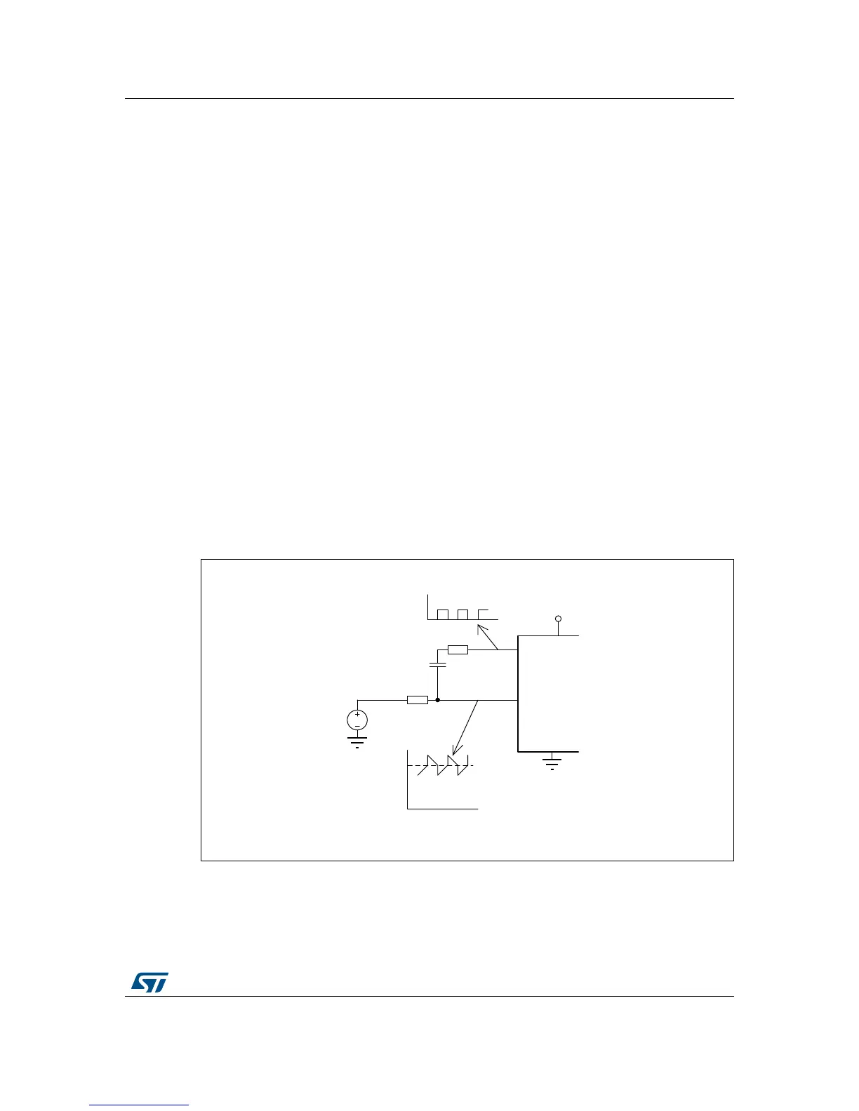
A very simple implementation of the quasi-triangular
source which is generated directly by
the STM32 microcontroller is on Figure 22.
Figure 22. Simple quasi-triangular source using a microcontroller output

 Loading...


