EasyManuals Logo

ST STM32 Application Note

ST STM32
49 pages
To Next Page IconTo Next Page
To Previous Page IconTo Previous Page
Page #39 background imageLoading...
Page #39 background image
DocID15067 Rev 3 39/49
AN2834 How to get the best ADC accuracy
48
3.4 High impedance source measurement
This section describes the ADC measurement behavior of STM32 ADC when a signal
source with high internal impedance is used. It explains how to design an application to
reach the requested precision and provides workarounds.
3.4.1 ADC input stage problem
The ADC embedded in STM32 devices is a switched-capacitor ADC. Switched capacitors
work also as sampling capacitors (see Section 1.1 for a detailed explanation).
When a signal comes from a voltage source with high internal impedance (for instance,
150 kΩ), an additional error can be seen in measurement results. Error signals have also
b
een observed on the ADC input pin, as shown in Figure 33 (if the voltage source has zero
voltage: U
in
= 0 V, R
in
= 150 k, C
ext
= 0 pF):
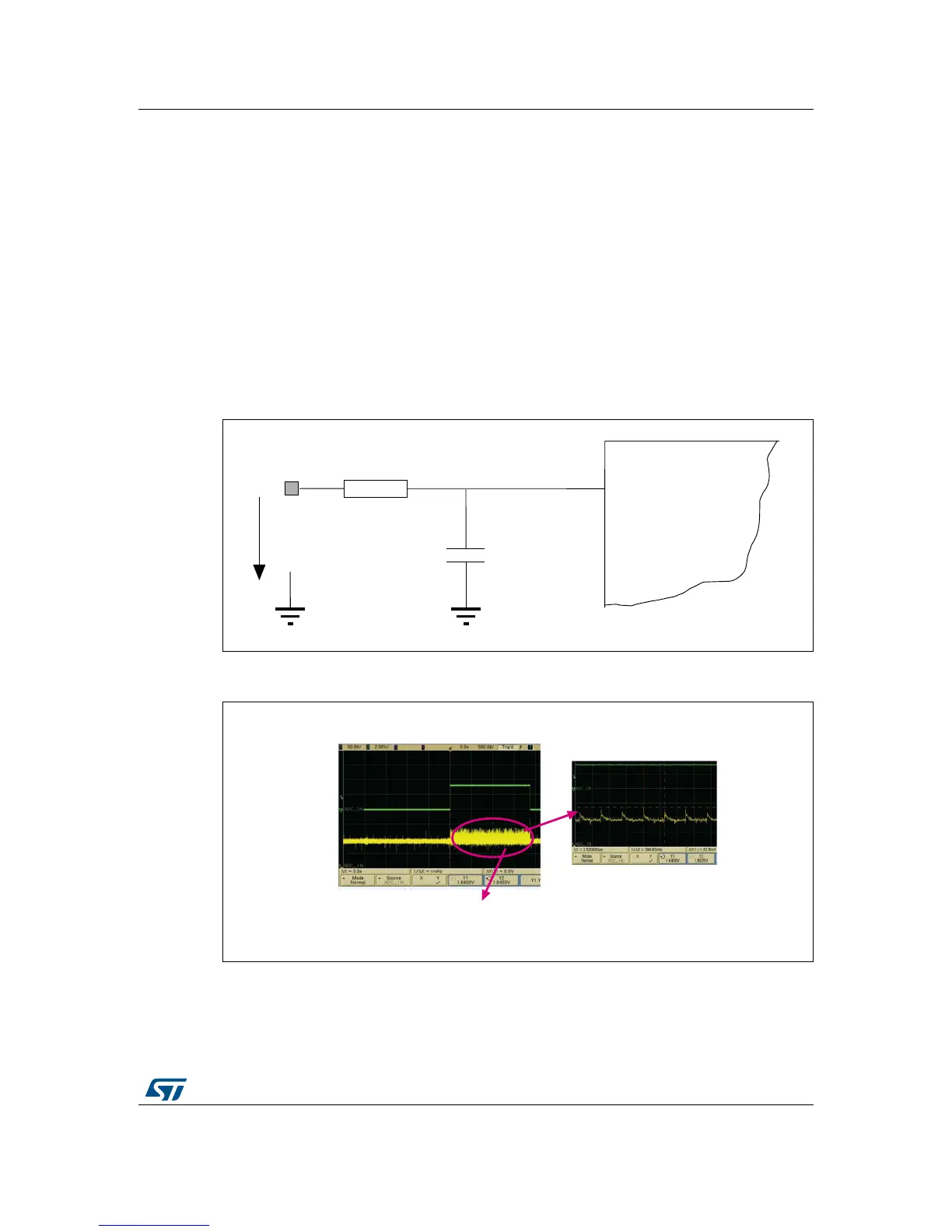
Figure 31. Typical voltage source connection to ADC input
Figure 32. Noise observed on ADC input pin during ADC conversions
$'&LQSXW
DLE
670
8
LQ
5
LQ
&
H[W
DLE
$'&LQSXWVLJQDOGXULQJFRQYHUVLRQ
ĂŶŶŽŝƐĞŝƐŝŶũĞĐƚĞĚƚŽƚŚĞŝŶƉƵƚ

Table of Contents

Other manuals for ST STM32

Questions and Answers:

Question and Answer IconNeed help?

Do you have a question about the ST STM32 and is the answer not in the manual?

ST STM32 Specifications

General IconGeneral
SeriesSTM32
CategoryMicrocontrollers
CoreARM Cortex-M0, Cortex-M0+, Cortex-M3, Cortex-M4, Cortex-M7, Cortex-M33
Clock SpeedUp to 480 MHz
GPIO PinsUp to 144
Communication InterfacesI2C, SPI, USART, USB, CAN, Ethernet
Package TypesLQFP, BGA, WLCSP
ADC Resolution12-bit, 16-bit (varies by series)
DAC Resolution12-bit (varies by series)
Operating Temperature-40°C to +85°C or +105°C

Related product manuals