DocID15067 Rev 3 11/49
AN2834 ADC errors
48
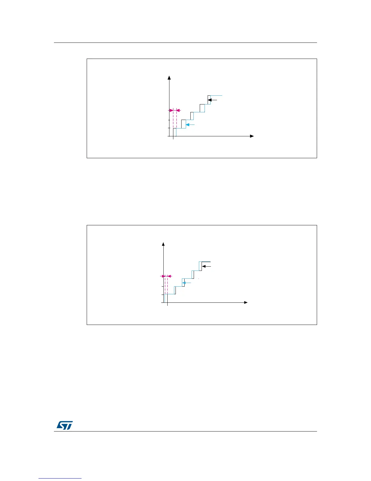
Figure 7. Positive offset error representation
1. The error offset, E
O
, is shown in magenta.
When an analog input voltage of less than 0.5 LSB generates the first transition, the offset
error is negative (refer to Figure 8 for an example of negative offset error).
If the analog input voltage (V
AIN
) is equal to V
SSA
and the ADC generates a non-zero digital
output, the offset error is negative. This means that a negative voltage generates the first
transition.
Figure 8. Negative offset error representation
1. The error offset, E
O
, is shown in magenta.

 Loading...


