www.stryker.com SM-7100 REV 01 49
Service
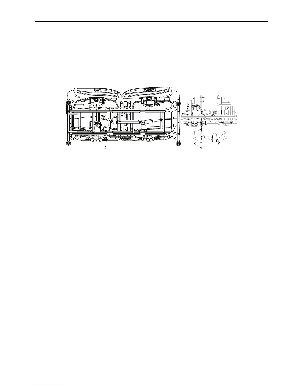
Gatch (legrest) actuator replacement (Continued)
5. Using diagonal pliers, cut the cable tie that secures all of the actuator cables together.
6. Discard the cable tie.
7. Using a small flat screwdriver, push in on the cable retainer clips on the controller to release the retainer.
8. Unplug the gatch (legrest) actuator cable to allow the removal of the gatch (legrest) actuator (A).
9. Using snap ring pliers, remove and discard the retaining rings (B) (Figure 3 on page 49) from the foot end clevis pin.
Remove and discard the retaining ring on the head end clevis pin.
Figure 3: Gatch (legrest) actuator
10. Using one hand, support the gatch (legrest) actuator and remove the foot end clevis pin (C) (Figure 3 on page 49)
and spacers then allow the gatch (legrest) actuator to pivot down.
11. Using one hand, support the gatch (legrest) actuator and remove the head end clevis pin (D) (Figure 3 on page 49).
12. Remove and discard the gatch (legrest) actuator.
13. Reverse steps to reinstall.
14. Verify proper operation of the product before returning it to service.
Head end lift actuator replacement
Tools required:
• Small flat screwdriver
• 90 Degree snap ring pliers (small)
• Diagonal pliers
Procedure:
1. Apply the brakes.
2. Support the head end litter cross brace (A) to support the head end litter (Figure 4 on page 50).
3. Power down the bed and unplug the power cord from the wall outlet.
4. Using diagonal pliers, cut the cable tie that secures the head end lift actuator cable.
5. Discard the cable tie.
6. Using a small flat screwdriver, gently push in both locking tabs to remove the cable retainer on the head end lift
actuator electrical connector.
7. Unplug the connector.
8. Using snap ring pliers, remove and discard the retaining ring (C) on each clevis pin (Figure 4 on page 50).
9. Using one hand, support the head end lift actuator and remove the head end clevis pin (D) then allow the head end
lift actuator (B) to pivot down (Figure 4 on page 50).
10. Using one hand, support the head end lift actuator and remove the foot end clevis pin (E) (Figure 4 on page 50).
11. Remove and discard the head end lift actuator.
12. Reverse steps to reinstall.