4-18 Sun StorEdge 3000 Family Installation, Operation, and Service Manual • May 2004
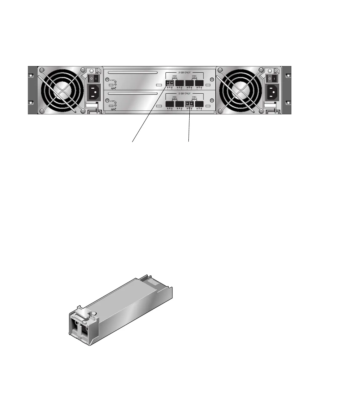
In a default Sun StorEdge 3511 FC expansion unit, SFPs are initially plugged into the
left-most Loop A port in the upper I/O expansion module and in the left-most Loop
B port in the lower I/O expansion module (
FIGURE 4-16).
FIGURE 4-16 Sun StorEdge 3511 Expansion Unit Default SFP Placement
4.6.4 Changing Your SFP Configuration
Sun StorEdge 3510 and 3511 FC arrays use SFP connectors to attach to hosts and
expansion units. These SFP connectors resemble the one shown in
FIGURE 4-17, with a
single connector at the end that plugs into an SFP port on the array or expansion
unit chassis, and a duplex jack into which you insert a cable to make the connection.
■ To make connection to an empty port, first slide the SFP connector into the port so
that it connects firmly with the chassis. Then plug the fiber-optic cable’s SFP
connector into the duplex jack at the end of the SFP.
■ To remove an SFP connector, remove the cable if one is connected to it, and then
slide the SFP out from the port.
FIGURE 4-17 Typical SFP Connector Used to Connect Cables to Chassis SFP Ports
Default SFP Placement

 Loading...


