42 SUNFAR C300
C300 series of non-sensor current vector-control inverter manual
Instruction Stop instruction FWD instruction REV instruction
Ter minal s
State
1: Two-line mode 2
Instruction Stop instruction Run instruction FWD instruction REV instruction
Ter minal s
State
2:Three-line mode
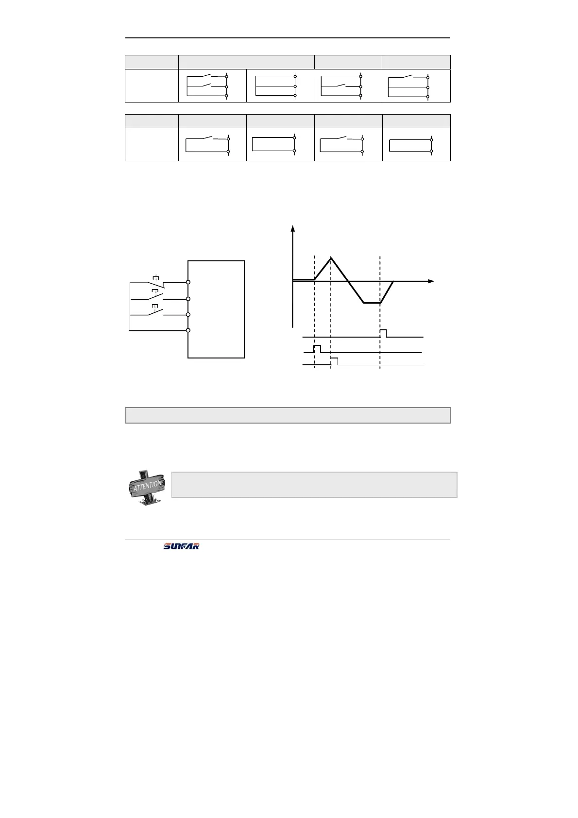
Please select a three-line mode terminal to set three-line mode. (Refer to
description of parameters F3.0 ~ F3.3) X?is three-line mode terminals,and it is
any one among terminals X1 ~ X4.
Switch function is shown as follows:
1. SW1 ——Stop trigger switch of inverter
2. SW2 ——
FWD trigger switch
3. SW3 ——
REV trigger switch
This parameter is used for modifying the present output phase sequence of inverter,
which modifies the running motor direction. Control effect of panel control method
is shown as the following table.
Fig.6-1 three-line mode wiring
SW1
SW2
SW3
X?
FWD
REV
GND
Fig.6-2 Output freq. when three-line
Output freq.
Time
SW1
SW2
SW3
FWD
REV
GND
FWD
REV
GND
FWD
REV
GND
FWD
REV
CM
FWD
GND
FWD
GND
REV
GND
REV
GND
F0. 6 Steering control Setting range:0000 ~ 0011
Parameter F0.4 is valid together with direction control of external terminals.