56 SUNFAR C300
C300 series of non-sensor current vector-control inverter manual
collector is open-circuit. Shown as fig.6-12.。
When TA is on with TC, setting functions will available.
0:In the running
When the inverter is in the running state, it will output the valid signal. While the
inverter is in stop mode, it will output the invalid signal.
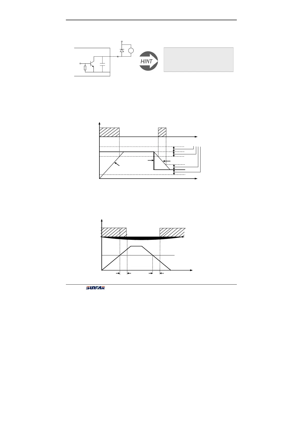
1:Frequency reaching
When the output frequency of inverter approaches the certain range of the setting
frequency. (The range is decided by parameter F3.6), it outputs valid signal,
otherwise, outputs the invalid signal (High-resistance).
2:Freq. level detection signal(FDT)
When the output frequency of inverter is over FDT Frequency level, the inverter
will output the valid signal (Low electrical level) after the setting delay time. When
the output frequency of inverter is lower than FDT frequency level, after the same
delay time, it will output the invalid signal (High resistance).
Fig.6-12 Inner wiring diagram of output terminals
R
1
2
D
While connecting the external
inductance cell (For example, Relay
coil), it must connect the parallel
fly-wheel diode D.
OC
f
High resistance
[F3.6]
t
Output freq.
Setting freq.
Output freq.
Fig.6-13 Freq. reaching signal
High resistance
High resistance
Setting frequency
OC1
t
.
[F3.7]
FDT Level
f
.
Fig. 6-14 Freq. level detection signal(FDT)