SUNFAR C300 57
C300 series of non-sensor current vector-control inverter manual
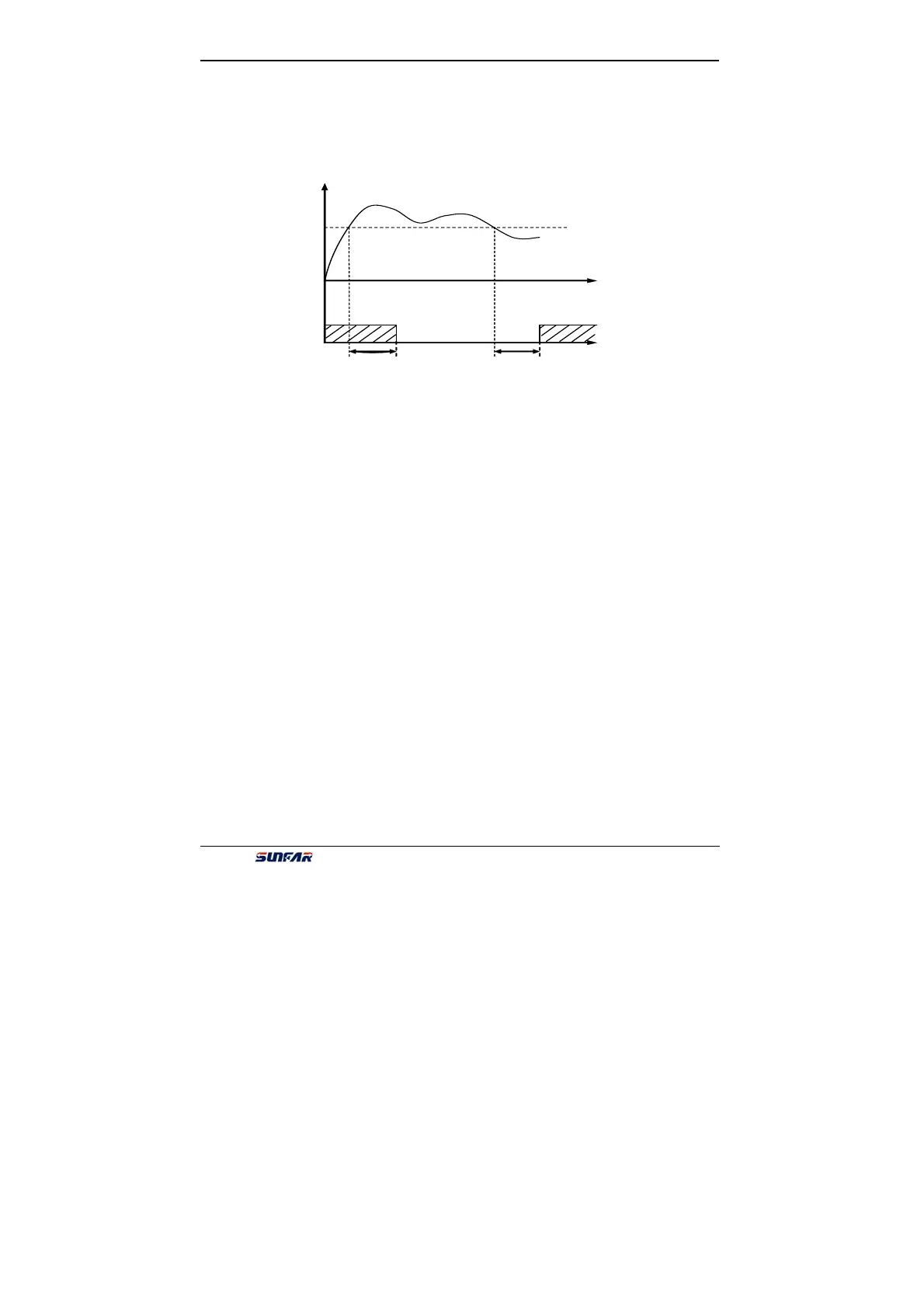
3. Over-loading alarm
When the output current of inverter is over the over-loading alarm level, it will
output the valid signal (Low level) after the setting alarm delay time. When the
output current is lower than the over-loading alarm level, it will output the invalid
signal (High resistance) after the same delay time.
4:External fault halt
When the external fault input signal is valid and it will lead to stop-machine, the
terminal will output the valid signal (Low level), otherwise it will output the invalid
signal (High resistance).
5:Output frequency reaches the upper-limit
When the output frequency reaches the upper-limit frequency, the terminal will
output the valid signal (Low level). Otherwise, it will output the invalid signal (High
resistance).
6:Output frequency reaches the lower-limit
When the output frequency reaches the lower-limit frequency, the terminal will
output the valid signal (Low level). Otherwise, it will output the invalid signal (High
resistance)
7:Running in zero speed
Running instruction is valid and output freq. is 0, if inverter is input freq., the
terminal will output the valid signal (Low electrical level). If inverter is not input freq.,
the terminal will output the invalid signal (High resistance).
8:Internal timer reaches the setting time
When the internal timer reaches the setting time, the terminal will output the valid
pulse signal of 0.5 Sec pulse widths. (Low electrical level)
9:PLC stage is end of run
When simple PLC is valid and current stage is end, this port will output pulse signal
with 0.5s pulse width. 10:PLC periodic is the end of running.
When simple PLC is valid and current period is end, this port will output pulse
signal with 0.5s pulse width.
11:Reserved
12:Setting value of counter arrives
Fig.6-15 Over-loading alarm
Output current
t
[F3.10]
OC
[F3.10]
Alarm
level
High resistance
High resistance