68 SUNFAR C300
C300 series of non-sensor current vector-control inverter manual
The parameter defines the counting action of internal counter, and the clock
terminals of counter are selected by parameter F1.6.
The counting value of counter for the external clock reaches the value appointed
by parameter F3.3, and the corresponding Terminal OC outputs a valid signal of
same width with the external clock cycle.
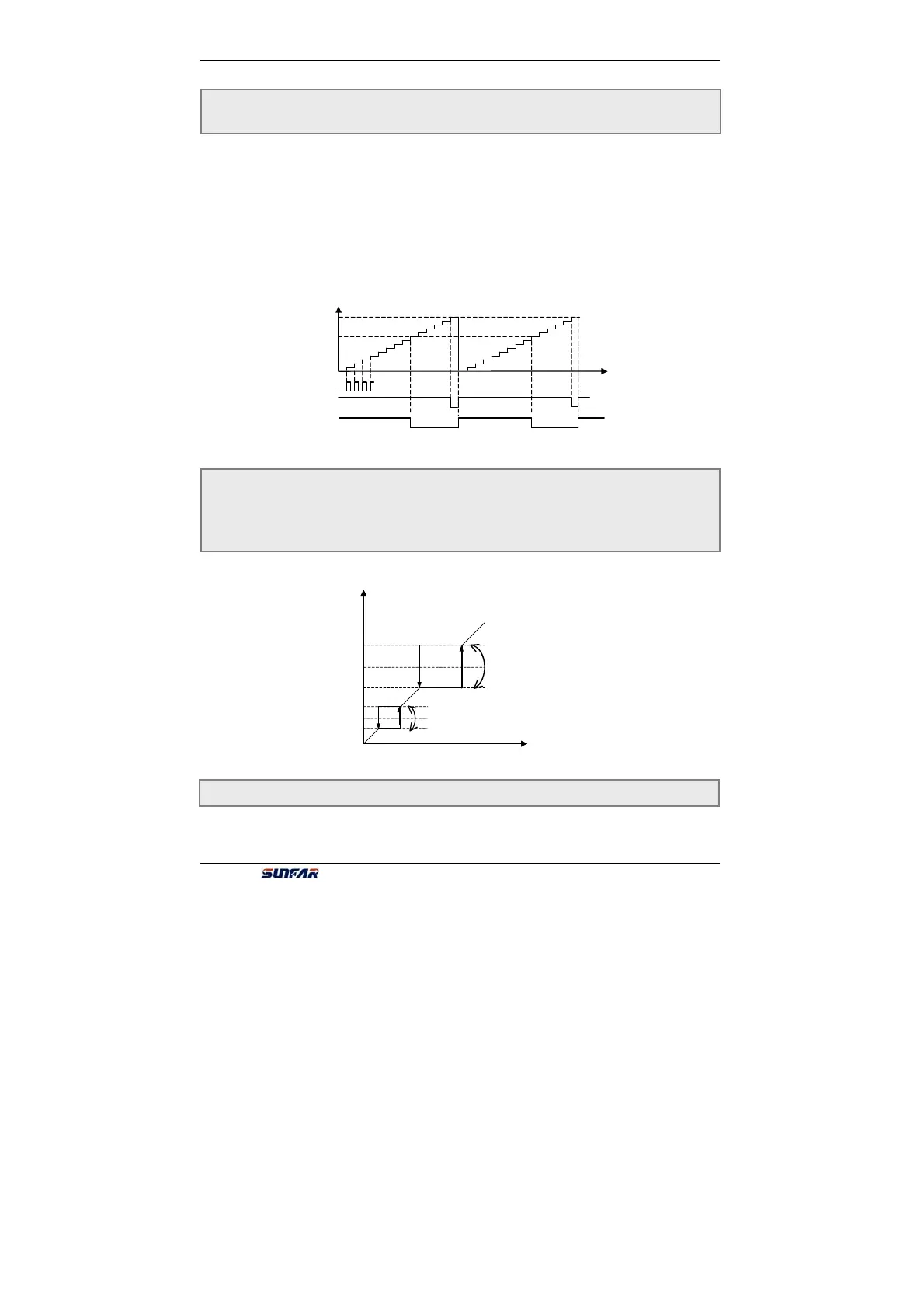
When the counting value of counter for external clock reached the value appointed
by Parameter F6.3, the corresponding Terminal OC will output the valid signal, Go
on counting to the value provided by parameter F6.4, which will lead to reset and
the output valid signal will be withdrawn.
The clock cycle of counter should be over 5ms and the min
width should be 2ms.
It is used for avoiding resonance point of mechanical lode. Shown as fig. 6-26.
This parameter is used for confirming the diapaly value of running linear speed and
F6.3 Final value setup of internal counter Setting range:1 ~ 60000
F6.4 Internal timer setup Setting range:1 ~ 60000
F6.5 Skip freq. 1 Setting range::0.0 ~ upper frequency
F6.6 Amplitude accumulation of Skip freq. 1 Setting range:0.0 ~ 5.00Hz
F6.7 Skip freq.2 Setting range:0.0 ~ upper frequency
F6.8 Amplitude accumulation of Skip freq. 2 Setting range:0.0 ~ 5.00Hz
F6.9 Coefficient of linear speed settings Setting range:0.01 ~ 100.0
[F6.3]
[F6.4]
OC
OC
Pluse
Fig.6-25 Internal counter function
mplitude accumulation of Skip freq. 2
Skip freq. 2
djusted setting freq.
Skip freq. 1
mplitude accumulation of Skip freq. 1
Fig.6-26 Skip freq.