78 SUNFAR C300
C300 series of non-sensor current vector-control inverter manual
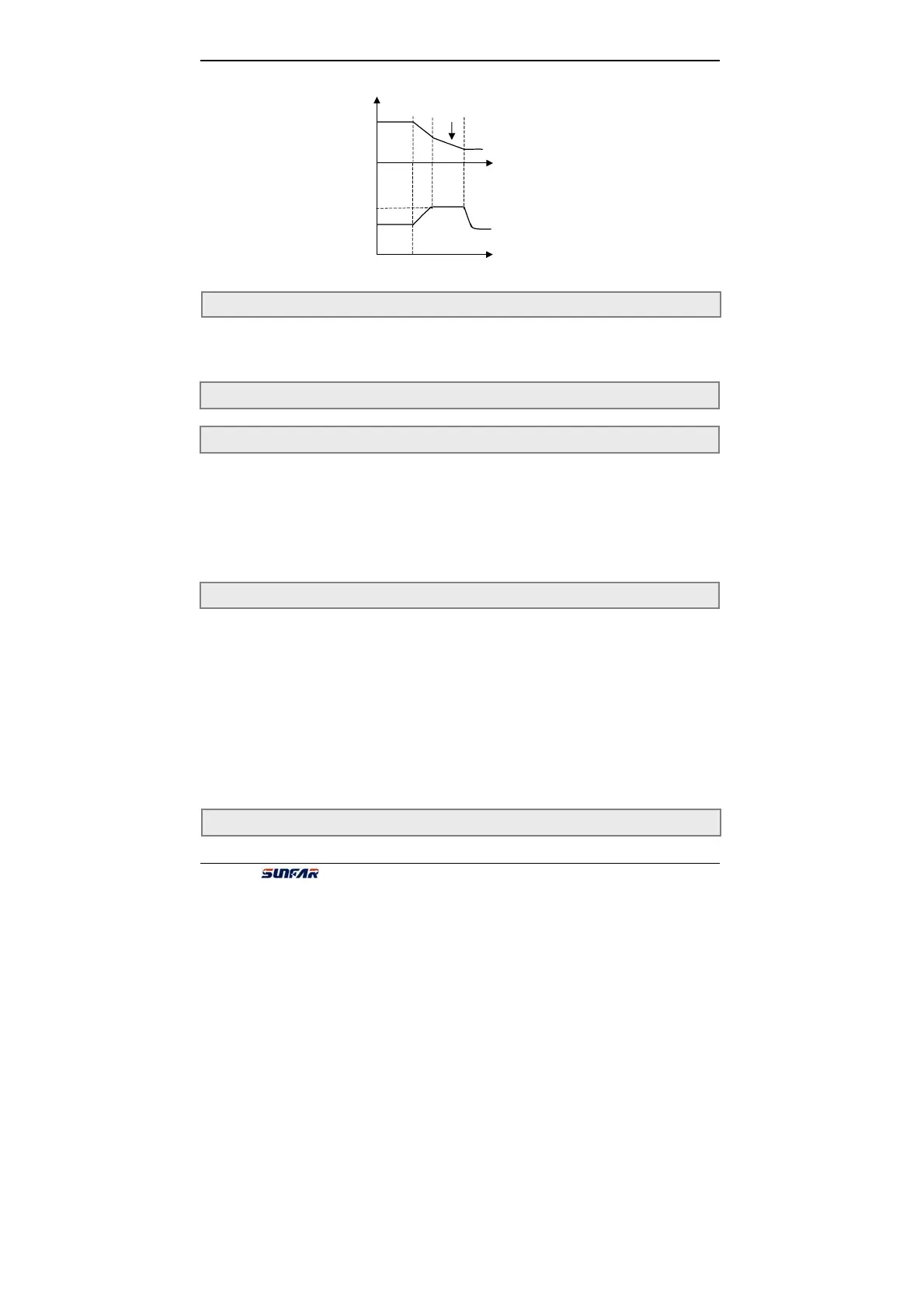
[FC.1]
f
t
djust Dec time
DC voltage
It defines the maximum output current which is permitted by inverter. Whatever the
operation mode is, inverter will adjust output freq. to inhibit current within the range
of regulation, when output current of inverter is beyond setting value of FC.2.
It is used for setting some coefficients with special function in running process.
Generally, user needn’t set.
The first part of LED(form right to left): Under voltage compensation intensity
The second part of LED: Over voltage inhibit intensity
The third part of LED: Over current inhibit intensity
The fourth part of LED:Self-adapting braking torque adjust intensity
The first part of LED(form right to left): Cooling fan control
0:Cooling fan run after inverter run.
Cooling fan will stop after inverter stop. When temperature is above 40℃,the
cooling fan also will also run.
1:Cooling fan will automatic run when inverter is power on.
The second part of LED: Variable speed control of cooling fan
0:Invalid
1:Valid
Cooling fan always keep the max speed.
The third part of LED: Voltage over modulation
0:Invalid 1:Valid
FC.3 Reserved
FC.2 Current amplitude limiting level Setting range: 150 ~ 200%
FC.4 Running protection function setting Setting range: 0000 ~ 9999
FC.5 Action function selection Setting range: 0000 ~ 0111
FC.6 Reserved
Fig.6-34 voltage stall protection in Dec speed