SINGLE PHASE HI 10/12kW | User Manual35
What this page displays:
Total solar power produced.
MPPT 1 power/voltage/current.
MPPT 2 power/voltage/current.
Grid power.
Grid frequency.
Grid voltage.
Grid current.
Inverter power.
Inverter frequency.
Inverter voltage.
Inverter current.
Load power.
Load voltage.
Battery power charge/discharge.
Battery SOC.
Battery voltage.
Battery current.
Battery temperature.
Solar Column: Shows total PV (Solar) power, voltage and current for each of the two MPPT.
Grid Column: Shows grid total power, frequency, voltage, and current. When selling power to the grid,
the power is negative. When consuming from the grid, the power is positive. If the sign of the grid and HM
(home) powers are not the same when the PV is disconnected and the inverter is only taking energy from the
grid and using the CT connected to Limit-2, then please reverse the polarity of the CT coil.
Important: See Section ‘Connecting the CT coil’.
Inverter Column: Showing inverter total power, frequency, L1, L2, voltage, current, and power.
Load Column: Showing total load power, load voltage, and power on L1 and L2.
Battery Column: Shows total power from the battery, battery SOC, battery voltage, battery current (negative
means charge, positive means discharge) battery temperature (shows zero if the battery temperature sensor
is not connected). DC transformer temperature and AC heatsink temperature (When the temperature reach-
es 90°C, it will display in red, and the performance of the inverter will start deteriorating when it reaches
110°C. Subsequently, the inverter will shut down to allow it to cool and reduce its temperature.
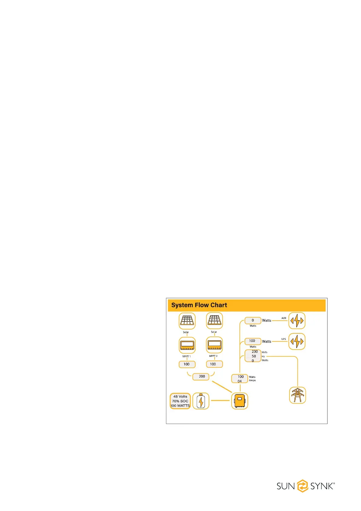
System Flow Page
Access by clicking on the bar chart on the
Home Page.
To better understand the functioning of
your system, take a look at the gure at
right:
1. The PV modules charge the batteries.
2. When the batteries reach a specic level
(programmable), the battery power is
fed into the inverter.
3. The inverter can then supply power to
the grid (export or no export), load, and
auxiliary or smart load.
4. CT coil controls the export power.
 Loading...