SINGLE PHASE HI 10/12kW | User Manual77
APPENDIX A
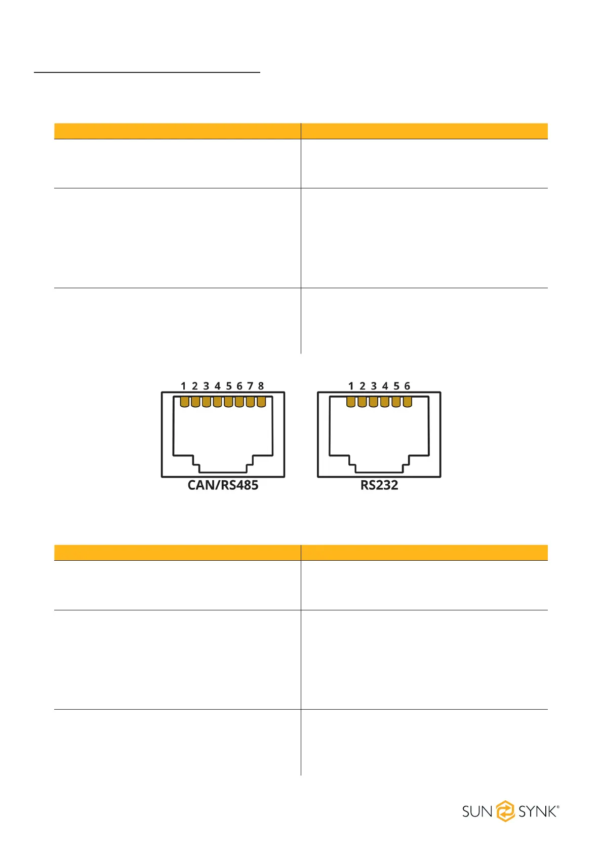
The following table is the connection on battery side of SSLB1:
Protocol Description
CAN
Pin 1: CAN-H
Pin 5: CAN-L
Pin 2, 3, 4, 6, 7, 8: NC
RS485
Pin 1: RS485B
Pin 2: RS485A
Pin 3, 6: GND
Pin 7: RS485A
Pin 8: RS485B
Pin 4, 5: NC
RS232
Pin 3: BMS transmit; Computer receiver
Pin 4: BMS receiver; Computer transmit
Pin 5: GND
Pin 1, 2, 6: NC
The following table is the connection on inverter side:
Protocol Description
CAN
Pin 4: CAN-H
Pin 5: CAN-L
Pin 1, 2, 3, 6, 7, 8: NC
RS485
Pin 1: RS485B
Pin 2: RS485A
Pin 3, 6: GND
Pin 7: RS485A
Pin 8: RS485B
Pin 4, 5: NC
RS232
Pin 3: BMS transmit; Computer receiver
Pin 4: BMS receiver; Computer transmit
Pin 5: GND
Pin 1, 2, 6: NC
 Loading...