OPERATION & MAINTENANCE MANUAL SWDE120B-3
2.4 Main Operating Interface
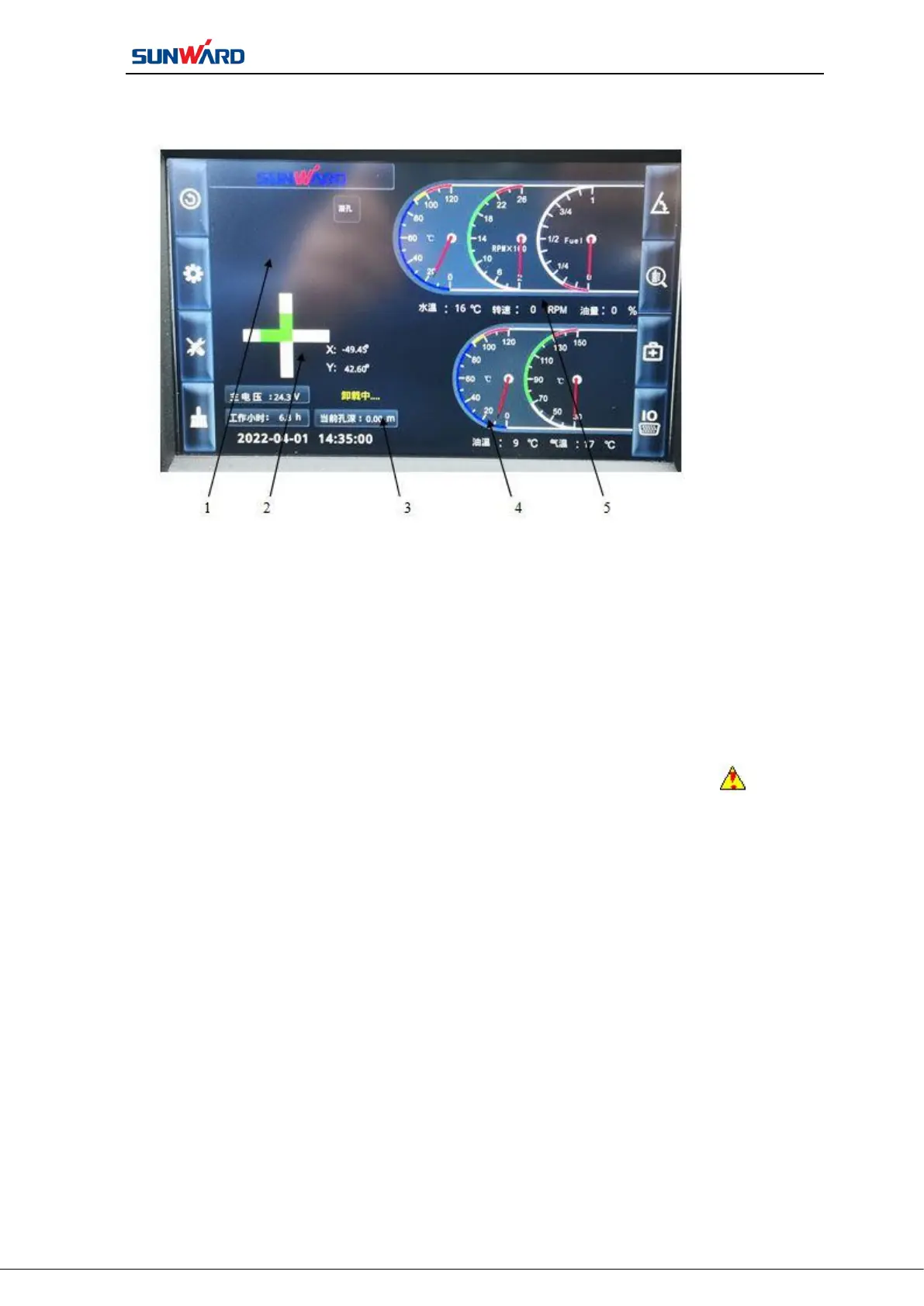
1. Fault code alarm 2. Inclination display
3. General parameters display 4. Air compressor parameters display
5. Host parameters display
Figure 3.2 Main Operating Interface
The main operation interface shows all the “fault alarm code” “inclination of drill
hole” “the operation parameters of the main engine” “the drilling depth” “the
running parameters of the air compressor”.
Icon 1 “fault code alarm” is the fault code alarm area. The alarm icon will flash
when a sensor of the machine fails or exceeds normal working range, prompting the operator
to inspect it. When the alarm appears, click icon F7“fault alarm code” on the main
operating interface to enter monitoring interface to check the detailed alarm. Then handle the
alarm situation, such as “engine oil pressure sensor alarm”, the operator will check the
engine lubrication system, troubleshooting.
Icon 2“inclination display” is the inclination display area of drill pipe. By installing
the inclination sensor on the drill rack, the current drilling pipe inclination data is displayed
in real-time in the interface after the sensor data conversion calculation.
Icon 3“general parameters display” is the general parameters display area of the
machine. The host system voltage, air compressor system voltage, current drilling depth, the
last drilling depth, hydraulic oil temperature and water tank level will be shown.
 Loading...