Istruction Manual for Operation and Maintenance SPX-960:
WARNING
During operation the STOP button must be pressed in
the event of real emergency conditions. When pressed,
it only stops the drive. During machine operation the
button must be released (disabled), otherwise it stops
all the controls.
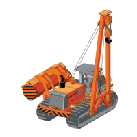
8) Orange light – diesel engine diagnostic (8 Fig. 27). This
light stays on for approx. 5 seconds when the diesel en-
gine is ignited; it goes off if the check is successful. The
light fl ashes for a preset number of times depending on
the alarm type (for decoding the typo of alarm refer to the
Instruction Manual for Operation and Maintenance of the
CATERPILLAR engine)
9) Horn button (9 Fig. 27).
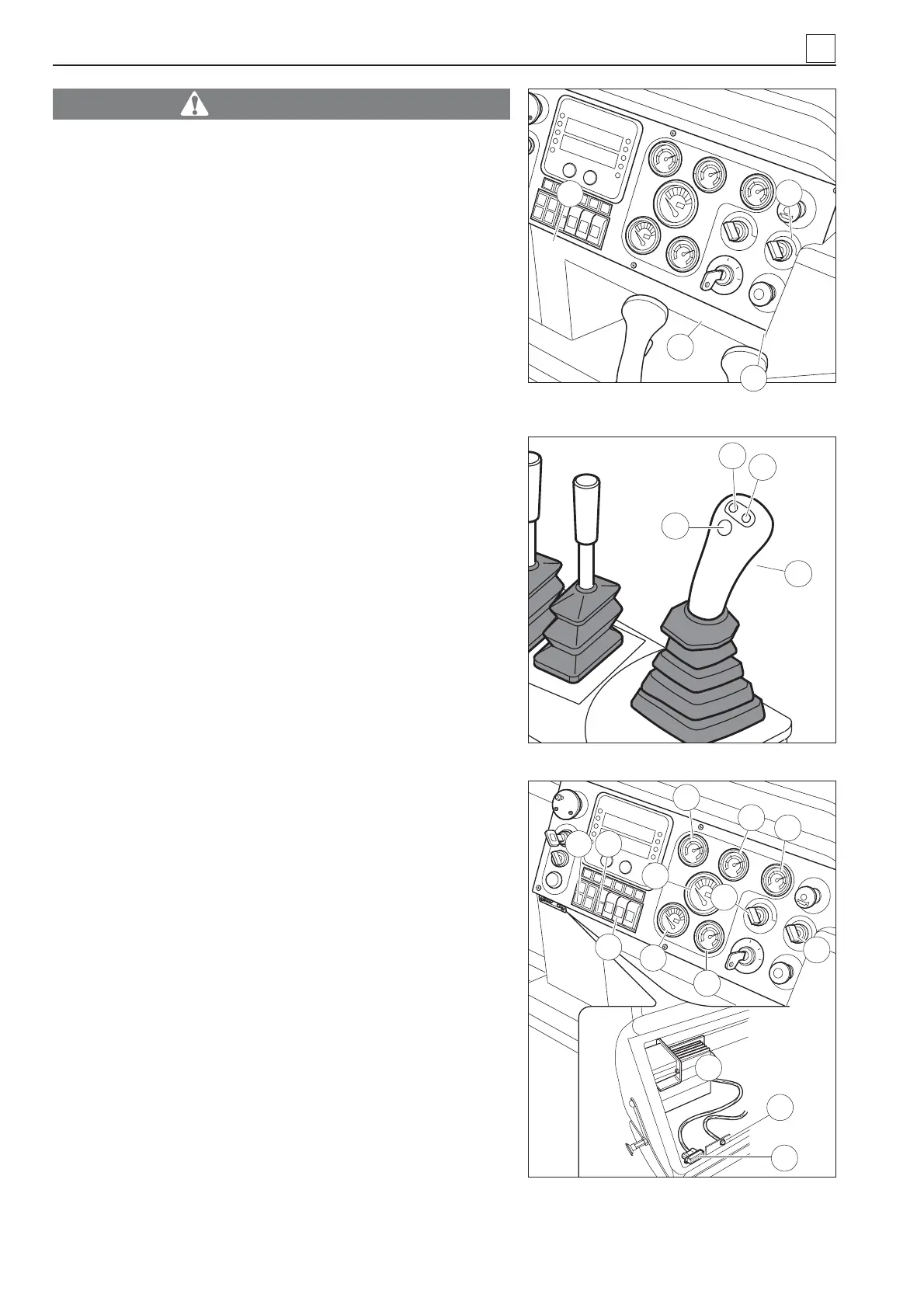
10) Diesel engine rpm presetting button (10 Fig. 28). Press
this button to set the diesel engine rpm at low speed (900
rpm).
11) Diesel engine rpm presetting button (11 Fig. 28). Press
this button to set the diesel engine rpm at medium-low
speed (1300 rpm).
12) Diesel engine rpm presetting button (12 Fig. 28). Press
this button to set the diesel engine rpm at medium-high
speed (1800 rpm).
13) Diesel engine rpm presetting button (13 Fig. 28). Press
this button to set the diesel engine rpm at high speed
(2100 rpm)..
14) Diesel engine rpm progressive accelerator/decelerator
button (14 in Fig. 29).
15) Two speed selector (15 Fig. 29) (fi rst and second gear
turning right).
16) Windscreen wiper switch forward (16 Fig. 29).
17) Light switch unit (front lights, taillights, lights on right and
left sides) (17 Fig. 29).
18) Preset rpm programming button (18 Fig. 29) (to be used
by service technicians only).
19) Parking button (19 Fig. 29). When the engine is turned
on, this button must be pressed, and the red light must
go on. When the button is in this position, the brakes are
engaged, the machine can be started up and the drive is
prevented from getting accidentally enabled.
20) Cooling water temperature indicator (20 Fig. 29).
4
4-10
Fig. 27 – Controls featured in standard
ATP system
8
Fig. 28
11
12
13
➤
10
9
7
6
14
17
43
46
18
16
20
24
25
22
19
21
23
15
MACHINE OPERATION
Fig. 29 – Controls featured in standard
ATP system