Istruction Manual for Operation and Maintenance SPX-960:
21) Engine oil temperature indicator (21 Fig. 29).
22) Engine oil pressure indicator (22 Fig. 29).
23) Volt meter (23 Fig. 29).
24) Hour meter (24 Fig. 29).
25) Fuel level indicator (25 Fig. 29).
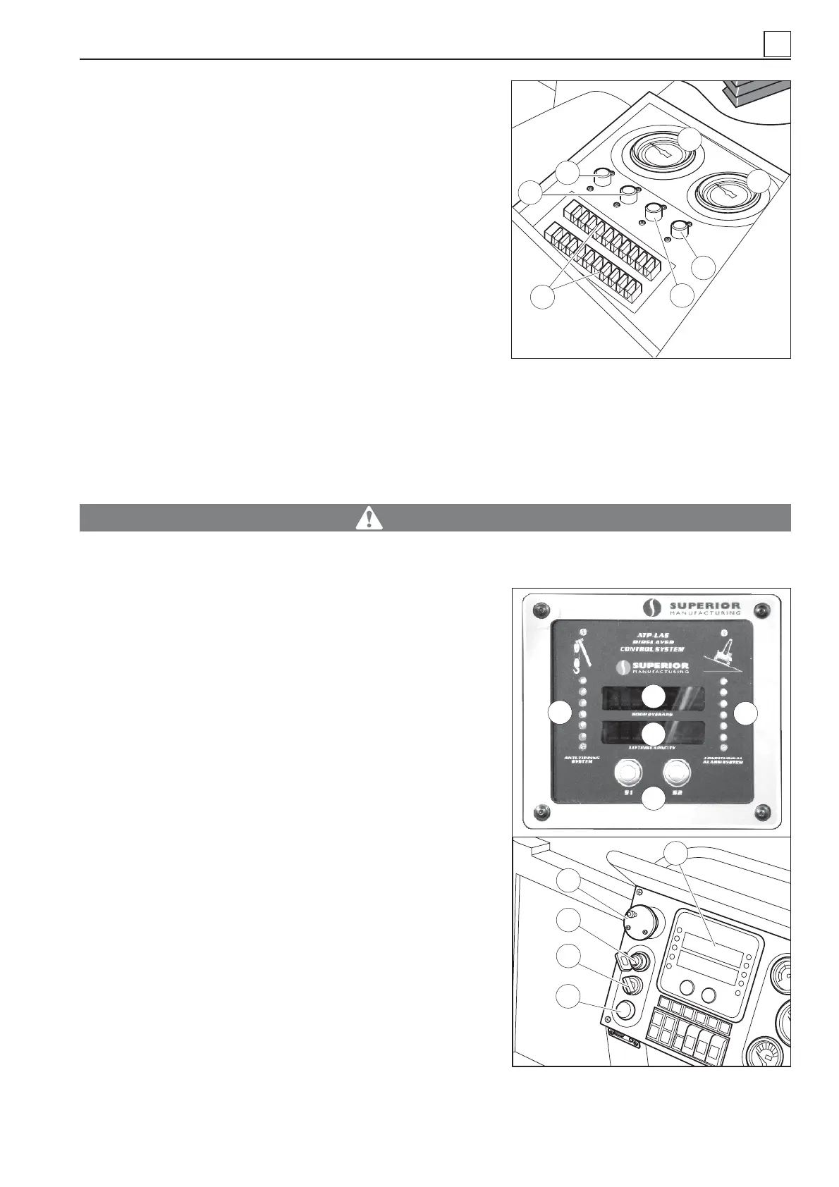
26) Left-hand drive booster pump gauge (26 Fig. 30) (indicates
low pressure).
27) Right-hand drive booster pump gauge (27 Fig. 30) (indi-
cates low pressure).
WARNING
The pressure values shown in the gauges (26 and 27 in Fig. 30) must constantly be around 22 to
25 bar. If there are strong variations in these values, or the pressure is either too high or low, im-
mediately refer to the Customer Service dept.
28) Temperature fuse 15A (28 Fig. 30) protecting the dashboard
indicators.
29) Temperature fuse 10A (29 Fig. 30) protecting the anti-tipping
system.
30) Temperature fuse 15A (30 Fig. 30) protecting the diesel en-
gine control unit.
31) Temperature fuse 60A (31 Fig. 30) protecting the ignition key
and right-hand dashboard instruments.
32) Fuse-holder blocks (32 Fig. 30).
33) Anti-tipping control panel ATP plus (STANDARD) (33 Fig. 31)
(refer to relevant instruction manual supplied separately).
34) FREE FALL BUTTON (Fig. 34 and 31). When this button is
pressed, the load is caused to free fall. Be very careful when
engaging this button. Use it in real emergency conditions
only.
4
Fig. 30
26
27
29
30
28
31
32
4-11
MACHINE OPERATION
45
44
38
39
35
36
37
34
➤
33
40
Fig. 31 – Controls featured in standard
ATP system