Istruction Manual for Operation and Maintenance SPX-960:
WARNING
When this button is pressed (34 in Fig. 31), the hook and
lifted load fall down freely (uncontrolled). This is why the
button must be used in serious emergency cases when
the risk exists that the machine tips over.
Make sure that free fall is compliant with the standards
and regulations existing in the country where the machine
is operated.
35) Anti-tipping system bypass key (Fig. 35 and 31). Turn
this key to override the safety functions of the anti-tipping
system.
WARNING
Utilize the bypass key functions only in real emergency
cases being fully aware of lifting operations.
In these conditions, in fact, the machine stability is not
controlled by the anti-tipping system.
37) Anti-tipping system power switch (Fig. 36 and 31). Turn the
switch to supply power to the anti-tipping system.
38) White light - electric system error (37 Fig. 31). This light
indicates that an electric error has occurred.
39) Yellow light - anti-tipping alert (38 Fig. 31). This light goes
on during lifting operations 15% before the max. lifting
capacity is reached (see yellow curve in the lifting capacity
diagram on page 15).
Red light . anti-tipping alarm (38 Fig. 31). This light goes on
during lifting operations 15% before the max. tipping curve
is reached (see red curve in the lifting capacity diagram
on page 15). This light is usually accompanied by a sound
signal (buzzer).
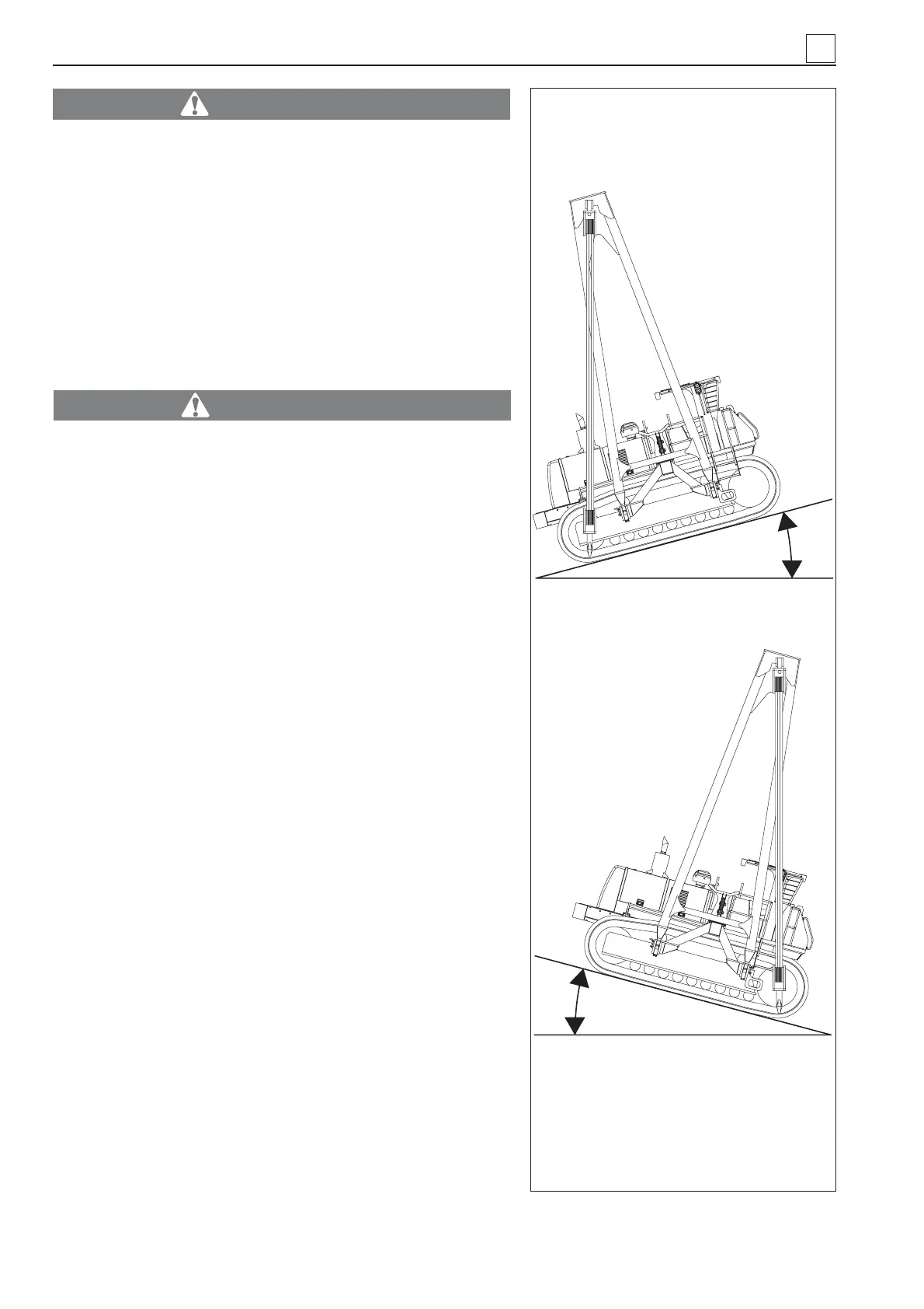
39) Longitudinal Alarm System (LAS) . longitudinal stability
indicator (39 Fig. 31). A number of green, red and yellow
LEDs turn on in this sequence depending on how seriously
affected machine longitudinal stability is.
This red lights are usually accompanied by a warning sound
signal (buzzer). This means that in this position the vertical
line of the hook is outside the machine support area (Fig.
32).
40) Buttons for setting control unit (40 Fig. 31).
4
Fig. 32
12°
12°
4-12
MACHINE OPERATION