Chapter 1: Introduction
1-5
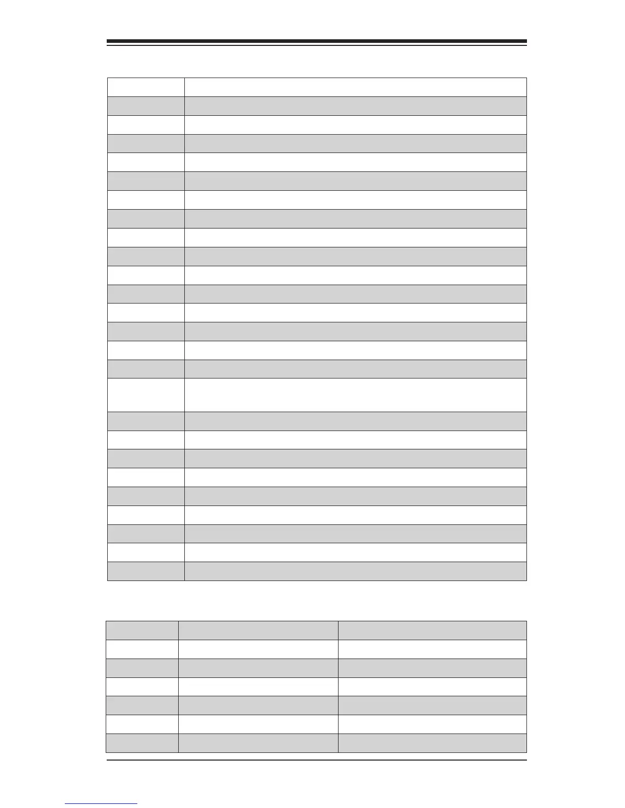
Jumper Descriptions
Ports, LEDs, and Connectors
JBR1 BIOS Recovery Pins 1-2 (Normal)
JBT1 CMOS Clear Short contact pads to reset CMOS
JI
2
C1/JI
2
C2 SMB to PCIe Slots Off (Disabled)
JPAC1 Audio Enable Pins 1-2 (Enabled)
JPME2 Intel ME Manufacturing Mode Select Pins 1-2 (Normal)
JWD1 Watch Dog Enable Pins 1-2 (Reset)
JPUSB1 USB Wake-Up Enable/Disable Pins 2-3 (Disabled)
Audio FP Front Panel Audio Header
AUDIO Ports Audio Connectors on the I/O backpanel. Not available on the X10SLV-Q.
Battery Onboard Battery
COM1/COM2 COM1 and COM2 Ports (on the I/O backpanel*)
COM3-COM5 COM3/COM4/COM5 Port Headers
Fan1-Fan3 System/CPU Fan Headers (Fan1: CPU Fan)
HDMI/DP DisplayPort (on the I/O backpanel)
JD1 Speaker/buzzer (Pins 3-4: Buzzer, Pins 1-4: External Speaker)
JF1 Front Panel Control Header
JL1 Chassis Intrusion Header
JPW1 24-pin ATX Power Connector
JPW2 12V 4-pin CPU power Connector (Required and alternative single power source.)
JSD1 SATA DOM (Device_On_Module) Power Connector
JTPM1 Trusted Platform Module (TPM) Header
LAN1/LAN2 Gigabit (RJ45) Ports LAN1 and LAN2 (on the I/O backpanel)
SP1 Internal Speaker/Buzzer
I-SATA0-3 X10SLV: (Intel-)Serial ATA (SATA 3.0) Ports 0-1 (6Gb/sec), Ports 2-3 (3Gb/s)
X10SLV:-Q (Intel-)Serial ATA (SATA 3.0) Ports 0-3 (6Gb/sec)
mini PCIE Mini PCIE Slot with mSATA support
Slot 1 PCI-Express 2.0 x16 Slot (X10SLV), PCI-Express 3.0 x16 (X10SLV-Q)
JGPIO 1 General Purpose I/O Expander Header
USB 0/1, 2/3 Backpanel USB 3.0 Ports 0/1 and USB 2.0 Ports 2/3
USB 4/5 Front Panel USB Header for USB 2.0 Ports 4/5
USB 10 Internal Type A USB 2.0 Port 10
DVI-I DVI (Combined Digital and Analog Video Interface) Port
JSMB1 System Management Bus (SMB) Header
LED1 Onboard Standby Power LED (Solid Green: Power On)