Engine Electrical Devices: 1C-6
6) Close the STV by finger, and measure the STP
sensor output voltage. If the output voltage is out of
the value, loosen the STP sensor mounting screw.
7) Adjust the STP sensor (3) until the output voltage
comes within the specified value and tighten the STP
sensor mounting screw.
Special tool
: 09930–11950 (Torx wrench)
8) Install the removed parts.
STP Sensor Removal and Installation
B705H11306026
Removal
1) Remove the helmet box front cover. Refer to “Helmet
Box Front Cover Removal and Installation in Section
9D (Page9D-16)”.
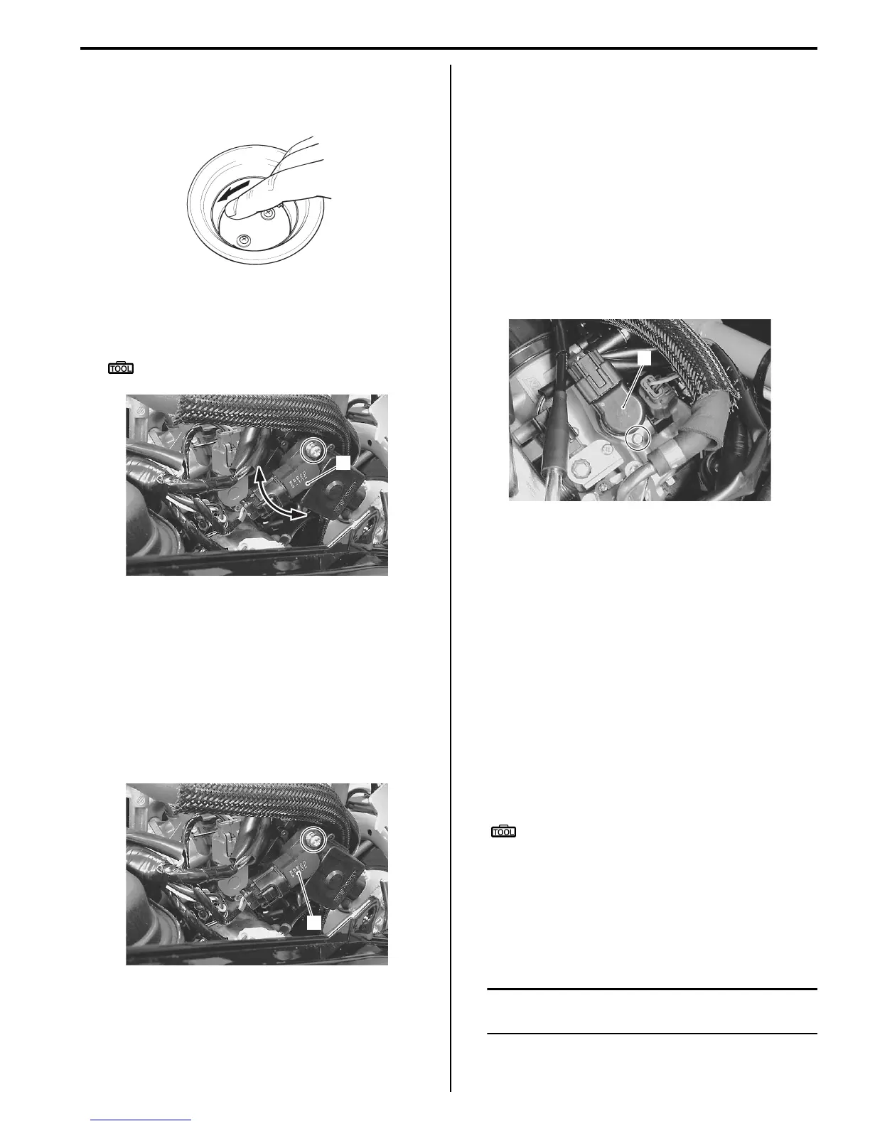
2) Disconnect the coupler and remove the STP sensor
(1).
Installation
Install the STP sensor in the reverse order of removal.
Pay attention to the following point:
• Adjust the position of STP sensor. Refer to “STP
Sensor Adjustment (Page1C-5)”.
ISC Valve Inspection
B705H11306027
Inspect the ISC valve. Refer to “DTC “C40” (P0505,
P0506 or P0507): ISC Valve Circuit Malfunction in
Section 1A (Page1A-55)”.
ISC Valve Removal and Installation
B705H11306028
Removal
1) Remove the helmet box front cover. Refer to “Helmet
Box Front Cover Removal and Installation in Section
9D (Page9D-16)”.
2) Disconnect the coupler and screw.
3) Remove the ISC valve (1).
Installation
Install the ISC valve in the reverse order of removal.
ISC valve pre-set
When removing or replacing the ISC valve, set the ISC
valve to the following procedures:
Procedure
1) Turn the ignition switch to OFF position.
2) Remove the upper meter panel. Refer to “Upper
Meter Panel Removal and Installation in Section 9D
(Page9D-13)”.
3) Connect the special tool to the dealer mode coupler
and turn its switch to ON position. Refer to “Self-
Diagnostic Procedures in Section 1A (Page1A-13)”.
Special tool
: 09930–82720 (Mode select switch)
4) Open the throttle valve fully and turn the ignition
switch to ON position.
5) Then, wait more than 10 seconds while holding the
4) condition.
6) Close the throttle valve and turn the ignition switch to
OFF position.
NOTE
The ISC valve is automatically set at PRE-
SET position.
7) Turn the special tool to OFF position and remove it
from the dealer mode coupler.
I705H1130013-01
3
I705H1130014-03
1
I705H1130016-01
1
I705H1130018-01
 Loading...


