1A-13 Engine General Information and Diagnosis:
Visual Inspection
Prior to diagnosis using the mode select switch or SDS, perform the following visual inspections. The reason for visual
inspection is that mechanical failures (such as oil leakage) cannot be displayed on the screen with the use of mode
select switch or SDS.
• Engine oil level and leakage. Refer to “Engine Oil and Filter Change in Section 0B (Page0B-9)”.
• Engine coolant level and leakage. Refer to “Cooling System Inspection in Section 0B (Page0B-11)”.
• Fuel level and leakage. Refer to “Fuel Line Inspection in Section 0B (Page0B-8)”.
• Clogged air cleaner element. Refer to “Air Cleaner Element Inspection in Section 0B (Page0B-3)”.
• Battery condition. Refer to “Battery Visual Inspection in Section 1J (Page1J-9)”.
• Throttle cable play. Refer to “Throttle Cable Play Inspection and Adjustment in Section 0B (Page0B-11)”.
• Broken fuse. Refer to “Precautions for Electrical Circuit Service in Section 00 (Page00-2)”.
• FI light operation. Refer to “Self-Diagnosis Function (Page1A-2)”.
• Each warning light operation. Refer to “Combination Meter Inspection in Section 9C (Page9C-2)”.
• Speedometer operation. Refer to “Combination Meter Inspection in Section 9C (Page9C-2)”.
• Exhaust gas leakage and noise. Refer to “Exhaust System Inspection in Section 1K (Page1K-4)”.
• Each coupler disconnection. Refer to “Precautions for Electrical Circuit Service in Section 00 (Page00-2)”.
Self-Diagnostic Procedures
B705H11104012
NOTE
• Do not disconnect coupler from ECM,
battery cable from battery, ECM ground
wire harness from engine or main fuse
before confirming DTC (Diagnostic Trouble
Code) stored in memory. Such
disconnection will erase memorized
information in ECM memory.
• DTC stored in ECM memory can be
checked by the special tool.
• Before checking DTC, read SELF-
DIAGNOSIS FUNCTION “USER MODE and
DEALER MODE” (Refer to “Self-Diagnosis
Function (Page1A-2)”) carefully to have
good understanding as to what functions
are available and how to use it.
• Be sure to read “PRECAUTIONS for
Electrical Circuit Service” (Refer to
“Precautions for Electrical Circuit Service
in Section 00 (Page00-2)”) before
inspection and observe what is written
there.
1) Remove the upper meter panel. Refer to “Upper
Meter Panel Removal and Installation in Section 9D
(Page9D-13)”.
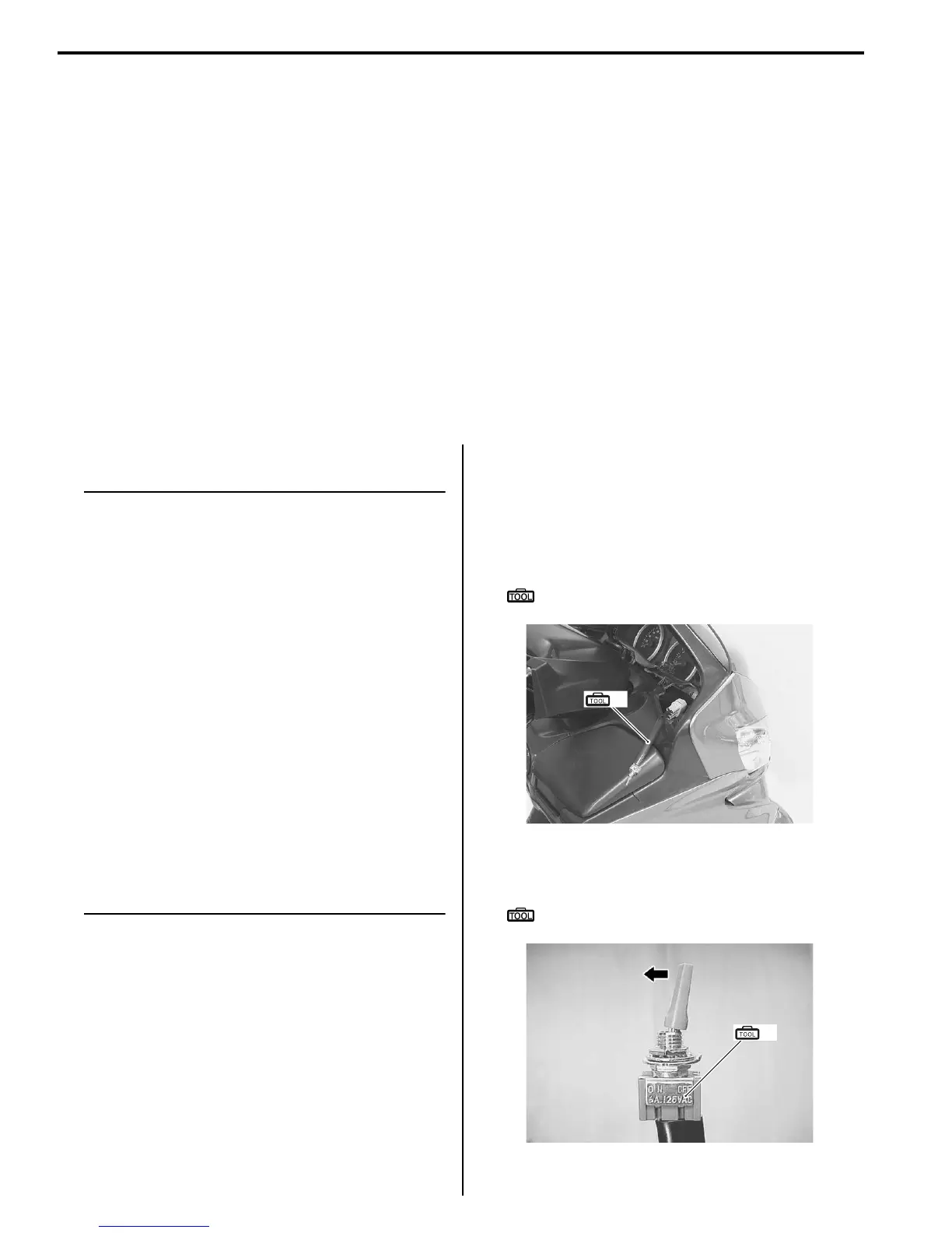
2) Connect the special tool to the dealer mode coupler
(A) at the wiring harness, and start the engine or
crank the engine for more than 4 seconds.
Special tool
(A): 09930–82720 (Mode select switch)
3) Turn the special tool’s switch ON and check the
malfunction code to determine the malfunction part.
Special tool
(A): 09930–82720 (Mode select switch)
(A)
I705H1110111-01
(A)
I705H1110114-01
 Loading...


