16 A-96.250.661 / 120418
AMI Sample Sequencer
Product Description
2.2.2 AMI Silitrace
The switch to the next channel is initiated by the AMI analyzer ac-
cording to the programmed switching time.
Example with two sample streams, switching time set to 30 min:
NOTICE:
• The different squares, black with/without underline and white
with/without underline are displayed on the display of the AMI
Sample Sequencer, for better understanding they are
integrated in the illustrations below.
• The meaning of the different squares is explained in
chapter 5, Operation.
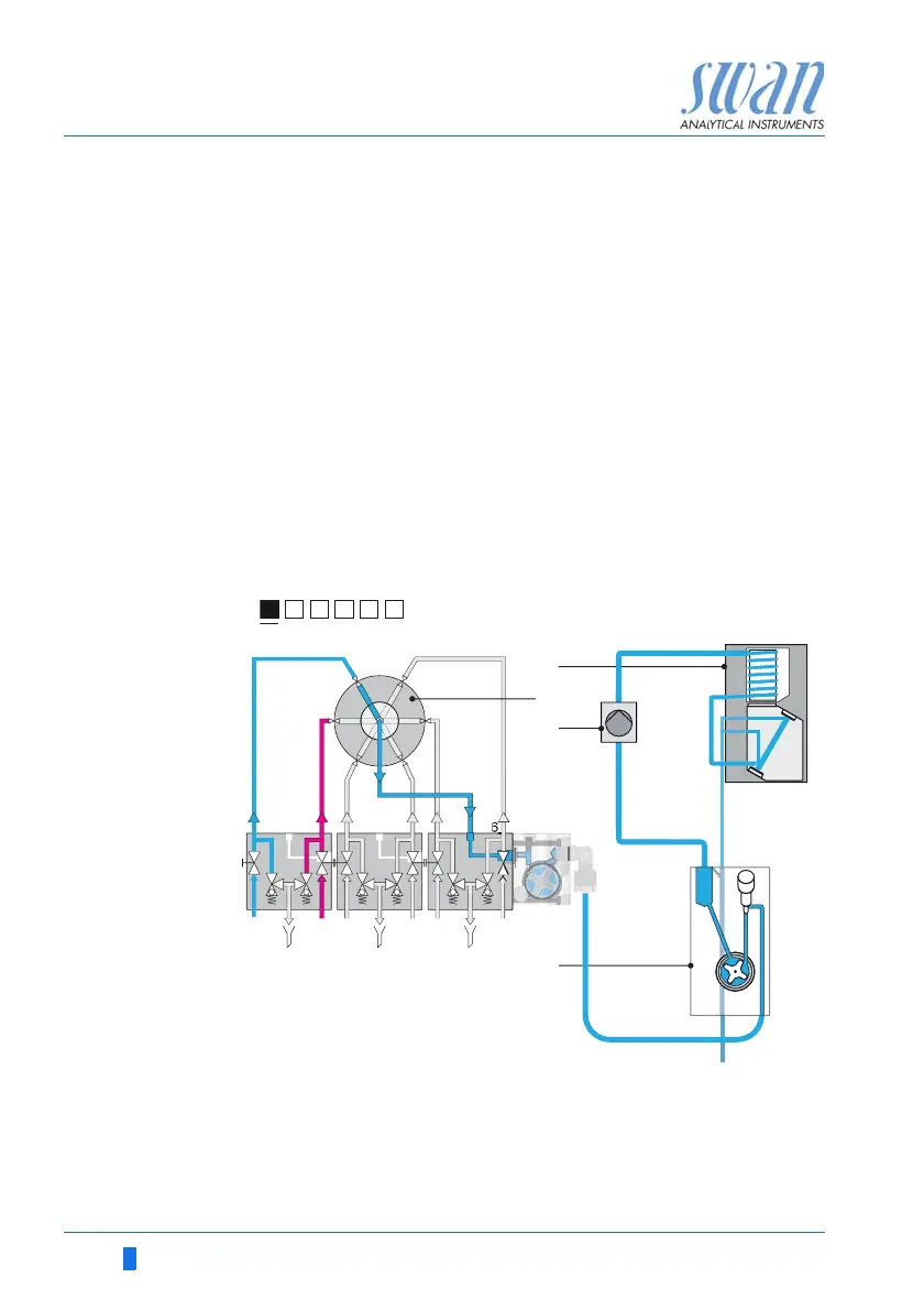
Step 1 The 6-way valve [B] is on position 1 and sample stream 1 flows
through the flow cell block [D]. From there, it is pumped to the
photometer by the peristaltic pump [C].
A
B
Photometer
6-way valve
C
D
Peristaltic pump
Flow cell block