AMI Sample Sequencer
Installation
A-96.250.661 / 120418 33
3.4.2 Sample Sequencer Inputs
Unused signal
inputs:
The following signal inputs of the AMI Sample Sequencer are not
applicable if an AMI analyzer is connected:
Signal inputs
from PLC
device:
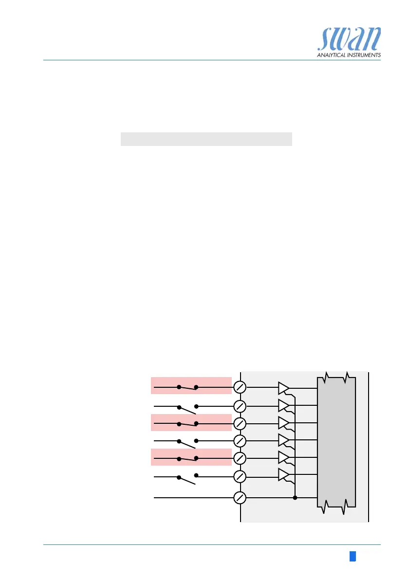
Each sample stream is assigned to an input channel of the
AMI Sample Sequencer. The sample stream number corresponds
with the channel number.
The functionality of the inputs depends on the settings of the Mode
of the AMI analyzer.
Mode Internal If the AMI analyzer is set to Mode Internal, the programmed num-
ber of sample streams is sequentially measured. Any sample inlet
can be deactivated by closing one or more of the contacts 9 to 14
(6 inputs from PLC) via a PLC.
In the example below, the channels highlighted in red will not be
measured.
NOTICE: If all contacts are closed, the AMI analyzer switches
to standby mode.
Terminals Signal
23/25 Mark end of measurement
27/29 System Alarm
34/32 Signal Input 1
31/32 Signal Input 2
CH1
SEQUENCER
Processor
CH2
CH3
CH4
CH5
6 Inputs from PLC
1 mA sink, 5 V open
CH6
GND
9
10
11
12
13
14
15