44 A-96.250.661 / 120418
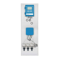
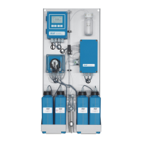
AMI Sample Sequencer
Installation
3.9. Communication, Error Handling
3.9.1 Mode <AMI>
The I
2
C connection allows a communication between the AMI ana-
lyzer and the AMI Sample Sequencer.
Sample Switch
Command
The AMI analyzer sends a command to the AMI Sample Sequencer
to switch the 6-way valve to the next sample stream.
Sample Flow
Error in
Mode Internal
If the Sample Sequencer detects a flow error on a sample stream, it
immediately switches to the next sample stream until it finds a sam-
ple stream with sample flow. The flow error is indicated on the re-
spective sample stream on the AMI analyzer display with a tilde.
During this time the AMI analyzer detects sample flow from the con-
stant head, therefore no flow alarm is triggered.
Sample Flow
Error in
Mode External
If the Sample Sequencer detects a flow error on a sample stream, it
is waiting for the command to switch to the next sample stream. A
flow alarm is issued via relay contact 7 “ALARM” of the outputs to
PLC.
3.9.2 Mode <Internal>
The signal outputs 1 and 2 of the AMI analyzer can be connected to
the signal inputs 1 and 2 of the AMI Sample Sequencer. This allows
to transfer the measuring values of each measured sample stream
to a remote device.
There is no communication between the AMI analyzer and the AMI
Sample Sequencer!
Sample Switch
Command
The command to switch to the next channel is triggered by the
AMI Sample Sequencer according to its programmed cycle time.
Sample Flow
Error
If the Sample Sequencer detects a flow error on a sample stream it
remains on this sample stream until the cycle time is over. During
this time it displays a flow alarm.