AMI Sample Sequencer
Product Description
A-96.250.661 / 120418 9
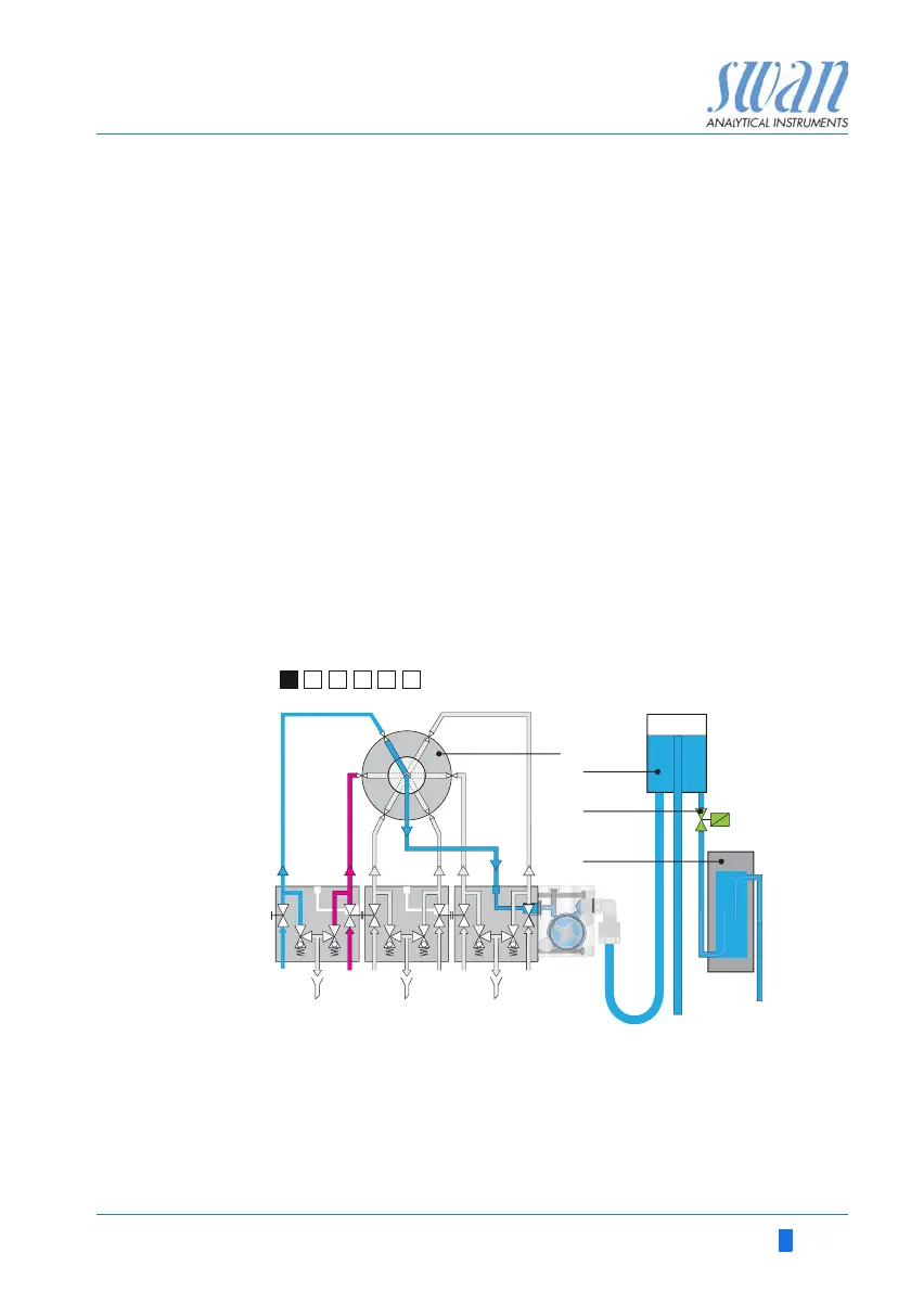
2.1. Measuring Cycle at Batch Measurement
2.1.1 AMI Silica and AMI Phosphate HL
Example with two sample streams:
A measuring cycle always starts when the solenoid valve [C] clos-
es.
NOTICE:
• The different squares, black with/without underline and white
with/without underline are displayed on the display of the AMI
Sample Sequencer, for better understanding they are
integrated in the illustrations below.
• The meaning of the different squares is explained in
chapter 5, Operation.
Step 1 The solenoid valve [C] is open.
The 6-way valve [A] is on position 1 and the sample stream 1
flows via constant head [B] through the photometer [D]. No
measurement is performed at this time.
A
B
6-way valve
Constant head
C
D
Solenoid valve
Photometer