36 A-96.250.661 / 120418
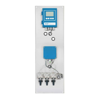
AMI Sample Sequencer
Installation
3.5. Connect the Instrument (Mode <Internal>)
The following instruction applies for the:
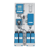
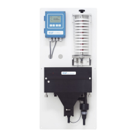
AMI Sodium A
AMI Sodium P
hereinafter referred to as AMI analyzer.
3.5.1 Connect the Two-Wire Signal Cable
The instruments listed above do not need any communication with
the AMI Sample Sequencer, therefore they are connected to the
AMI Sample Sequencer via a two wire signal cable from the signal
outputs of the AMI analyzer to the signal inputs of the AMI Sample
Sequencer.
NOTICE: If an AMI analyzer is already equipped with a 2
nd
Sample Stream option, it is not possible to operate it with an
AMI Sample Sequencer. Before connecting an AMI Sample
Sequencer remove the 2
nd
Sample Stream option.
WARNING
Risk of electrical shock
Do not perform any work on electrical components if the trans-
mitter is switched on. Failure to follow safety instructions could
result in serious injury or death.
Stop sample flow.
Shut off power of the analyzer.
1 Feed one cable end through a PG 7 cable gland into the trans-
mitter housing of the AMI analyzer and the other one into the
transmitter housing of the AMI Sample Sequencer.
2 Connect the cable to the terminals for signal output 1 and 2 of
the AMI analyzer according to the Connection Diagram, p. 42.
3 Connect the cable to the terminals for signal input 1 and 2 of the
AMI Sample Sequencer according to the Connection Diagram,
p. 42.