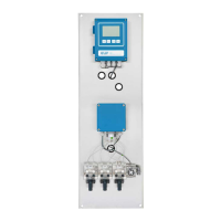
AMI Sample Sequencer
Installation
A-96.250.661 / 120418 31
3.4. Connect the Instrument (Mode <AMI>)
The following instruction applies for the:
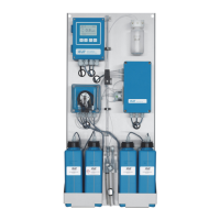
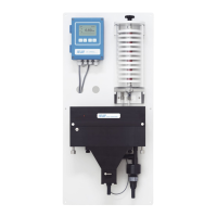
AMI Silica
AMI Silitrace
AMI Phosphate HL
hereinafter referred to as AMI analyzer.
3.4.1 Connect the I
2
C Bus
The AMI analyzers listed above require an I
2
C bus connection,
which allows communication between the two instruments.
WARNING
Risk of electrical shock
Do not perform any work on electrical components if the trans-
mitter is switched on. Failure to follow safety instructions could
result in serious injury or death.
Stop sample flow.
Shut off power of the analyzer.
Connect the AMI analyzer and the Sample Sequencer as follows:
1 Switch off the Instrument.
2 Open the transmitter cover.
3 Feed one cable end through a PG 7 cable gland into the trans-
mitter housing of the AMI analyzer and the other one into the
transmitter housing of the Sample Sequencer.
4 Connect the cable to the plugs according to the following table.
NOTICE: Due to technical reasons the data signal wires green
and white of the I
2
C bus need to be connected to the plug in
inverse order if the transmitter of the AMI analyzer is equipped
with main board V2.4.