1.3.1.2.2 Connecting a Brake
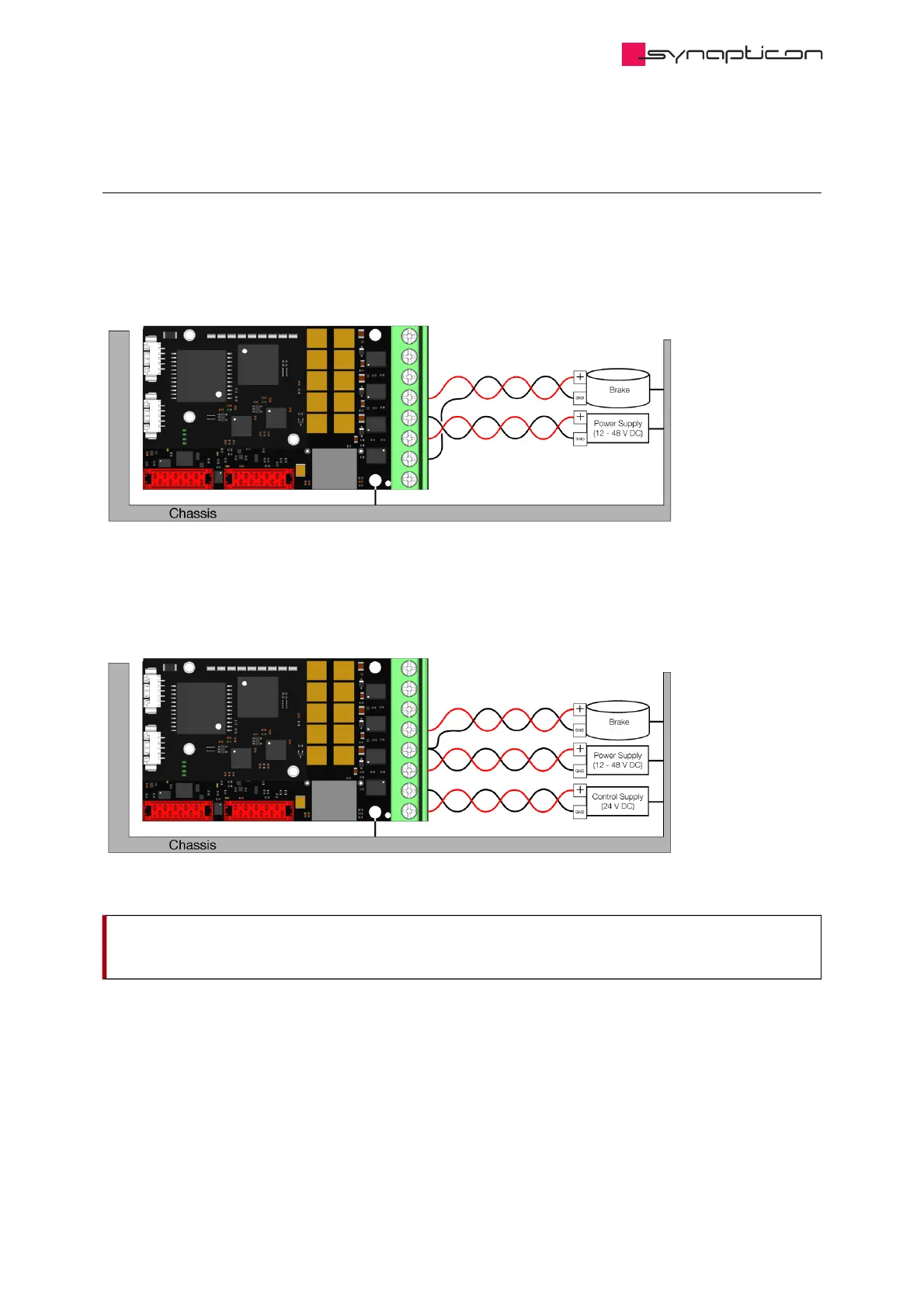
If your system has an attached brake, please connect the brake cables to Phase D and Ground. These
two threads should be twisted together or at least be paired to have a minimum area between them.
By default, Logic Supply is deactivated, it is therefore recommended to use Logic Ground (pin 7 of the
Main Supply Connector) for the brake.
If Logic Supply is active, Ground of the brake can be connected to the Ground cable of the 48V power
supply in a spot close to the board or it can be connected together with the Ground of the 48V supply to
the pin 5 of the Main Supply connector if they fit in there.
Important
Important
Please make sure the servo drive is properly grounded. You can connect the heatsink to ground.
Please make sure the servo drive is properly grounded. You can connect the heatsink to ground.